Figure 3: crossed cable rs-232 connection – Kramer Electronics 7508 User Manual
Page 9
Using Your 7508 CV/YC to SDI Converter
7
7
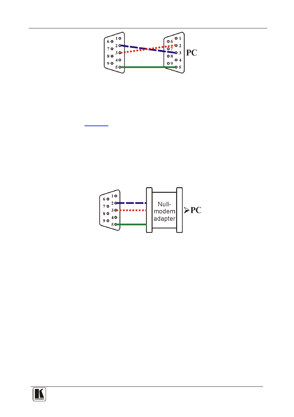
Figure 3: Crossed Cable RS-232 Connection
Hardware flow control is not required for this unit. In the rare case where a
controller requires hardware flow control, short pin 1 to 7 and 8, and pin 4
to 6 on the controller side.
Method B (
)—Connect the RS-232 9-pin D-sub port on the unit via
a straight (flat) cable to the null-modem adapter, and connect the null-
modem adapter to the RS-232 9-pin D-sub port on the PC. The straight
cable usually contains all nine wires for a full connection of the D-sub
connector. Because the null-modem adapter (which already includes the
flow control jumpering described in Method A above) only requires pins 2,
3 and 5 to be connected, you are free to decide whether to connect only
these 3 pins or all 9 pins.
Figure 4: Straight Cable RS-232 Connection with a Null Modem Adapter