Technical specifications, Installation instructions – Kramer Electronics RC-5B4 User Manual
Page 2
7. Retaining the orientation, place the button caps on the
buttons of the
RC-5B2 / RC-5B4.
8. Place the faceplate on the
RC-5B2 / RC-5B4 so that the
two screw mounting holes are aligned.
9. Insert the two mounting screws and tighten with a
screwdriver.
Figure 5: Placing the
Button Cap
Using the RC-5B2 and RC-5B4 K-NET Auxiliary Control Panel
The installation process is not detailed in this user manual. This user manual is applicable once the
unit is installed and configured (by authorized Kramer technical personnel or by an external system
integrator), and includes:
•
Setting up the labels on the buttons, according to your specific requirements
•
Configuration of the Master room controller via the
K-Config Windows
®
-based configuration
software
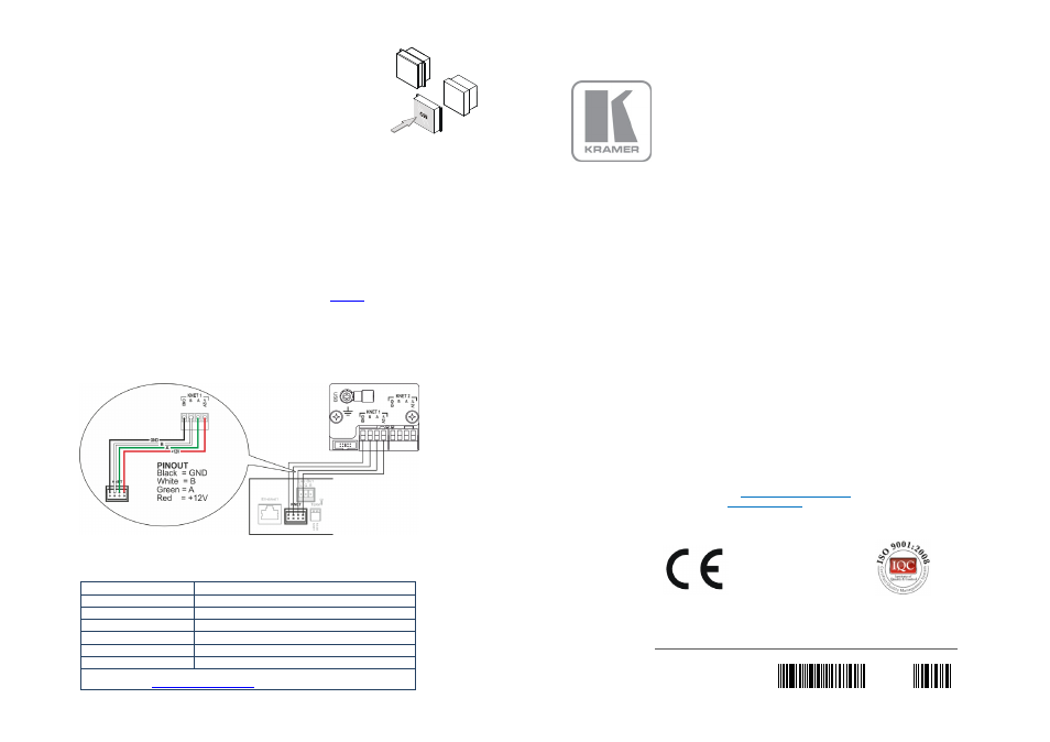
Since the auxiliary panel is used as a remote controller for Master Room Controllers via the
proprietary communication channel K-NET (as illustrated in
•
It requires only a K-NET connection to the Master Room controller
•
A power supply unit is
not required
•
The auxiliary panel can be programmed only via the Master Room controller (for example, the
Kramer
SV-551 SummitView™ Processor/Switcher)
Figure 6: connected to the SV-551 SummitView™ Processor / Switcher
Technical Specifications
PORTS:
2 K-NET on terminal block connectors; 1 USB for programming
POWER CONSUMPTION:
5V DC, 40mA
OPERATING TEMPERATURE:
0° to +55°C (32° to 131°F)
STORAGE TEMPERATURE:
-45° to +72°C (-49° to 162°F)
HUMIDITY:
10% to 90%, RHL non-condensing
DIMENSIONS:
5cm x 2.4cm x 4.7cm (1.97" x 0.94" 1.85") W, D, H.
WEIGHT:
0.14kg (0.31lbs) approx.
Specifications are subject to change without notice
Go to our Web sit
access the list of resolutions
KRAMER ELECTRONICS LTD.
Installation
Instructions
MODELS:
RC-5B2
Dual Insert
K-NET™ Auxiliary Control Panel
RC-5B4
Dual Insert
K
−NET™ Auxiliary Control Panel
For the latest information on our products and a list of Kramer
distributors, visit our Web site where updates to these
installation instructions may be found.
We welcome your questions, comments, and feedback.
Web site:
E-mail:
www.kramerelectronics.com
!
SAFETY WARNING
Disconnect the unit from the power
supply before opening and servicing
P/N: 2900-300128 Rev 2
P/N:
2900-300128
Rev:
2