Figure 2: tp-202 (underside panel) – Kramer Electronics TP-202 User Manual
Page 9
6
TP-202 - Overview
#
Feature
Function
1
EQ. Trimmer
Adjust the cable compensation equalization level
Insert a screwdriver into the small hole and carefully
rotate it, to trim the appropriate level
2
LEVEL Trimmer
Adjust the output signal level
3
UXGA OUT 1 15-pin HD Connector
Connect to the first UXGA acceptor
4
UXGA OUT 2 15-pin HD Connector
Connect to the second UXGA acceptor
5
ON LED
Illuminates when receiving power
6
LINE OUT RJ-45 Connector
Connect to the LINE IN connector on an additional
TP-202
Using a UTP CAT 5 cable with RJ-45 connectors at
both ends (the PINOUT is defined in
7
LINE IN RJ-45 Connector
Connect to the LINE OUT RJ-45 connector on the
transmitter
For example, the PT-110, as
illustrates
8
12V DC
+12V DC connector for powering the unit
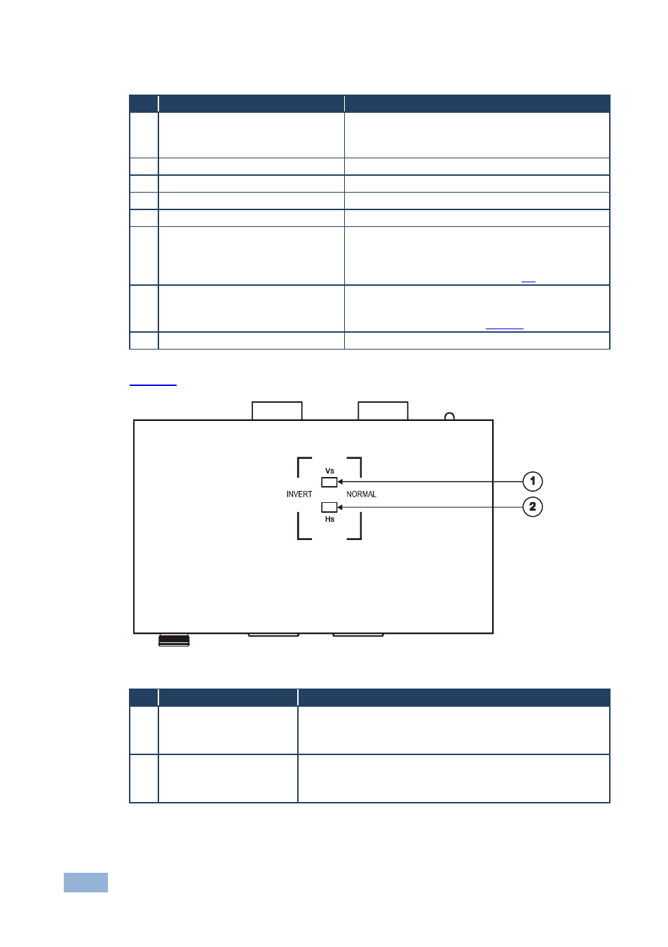
defines the TP-202 underside panel:
Figure 2: TP-202 (Underside Panel)
#
Feature
Function
1
VS Switch
Slide the switch to NORMAL to retain the polarity
Slide the switch to INVERT to invert the VS polarity
By default, both switches are set to NORMAL
2
HS Switch
Slide the switch to NORMAL to retain the polarity
Slide the switch to INVERT to invert the HS polarity
By default, both switches are set to NORMAL