Figure 2 and table 2 define the underside controls – Kramer Electronics VP-108 User Manual
Page 7
Your VP-108 1:8 XGA / Balanced Stereo Audio DA
5
Table 1: VP-108 1:8 XGA / Balanced Stereo Audio DA Features
#
Feature
Function
1
POWER
Switch
Illuminated switch for turning the unit ON or OFF
2
AUDIO INPUT
Terminal Block
Connector
Connect to the balanced stereo audio source
3
XGA INPUT
15-pin HD Connector
Connect to the XGA source
4
LEFT LEVEL
Trimmer
Adjust
1
the left output signal level
5
RIGHT LEVEL
Trimmer
Adjust
1
the right output signal level
6
LOOP
15-pin HD Connector
For looping to increase output availability
7
OUTPUT
Terminal Block Connectors
Connect to the balanced stereo audio acceptors (from 1 to 8)
8
OUTPUT
15-pin HD Connectors
Connect to the XGA
acceptors (from 1 to 8)
9
REMOTE Terminal Block Connectors
Connect to the contact closure switches
10
RS-485
Connector
RS-485 detachable terminal block port
11
RS-232
9-pin D-sub Connector
Connect to PC or other Serial Controller
12
SETUP Dipswitches
Dipswitches for setup of the unit
13
Power Connector with
Fuse
AC connector enabling power supply to the unit
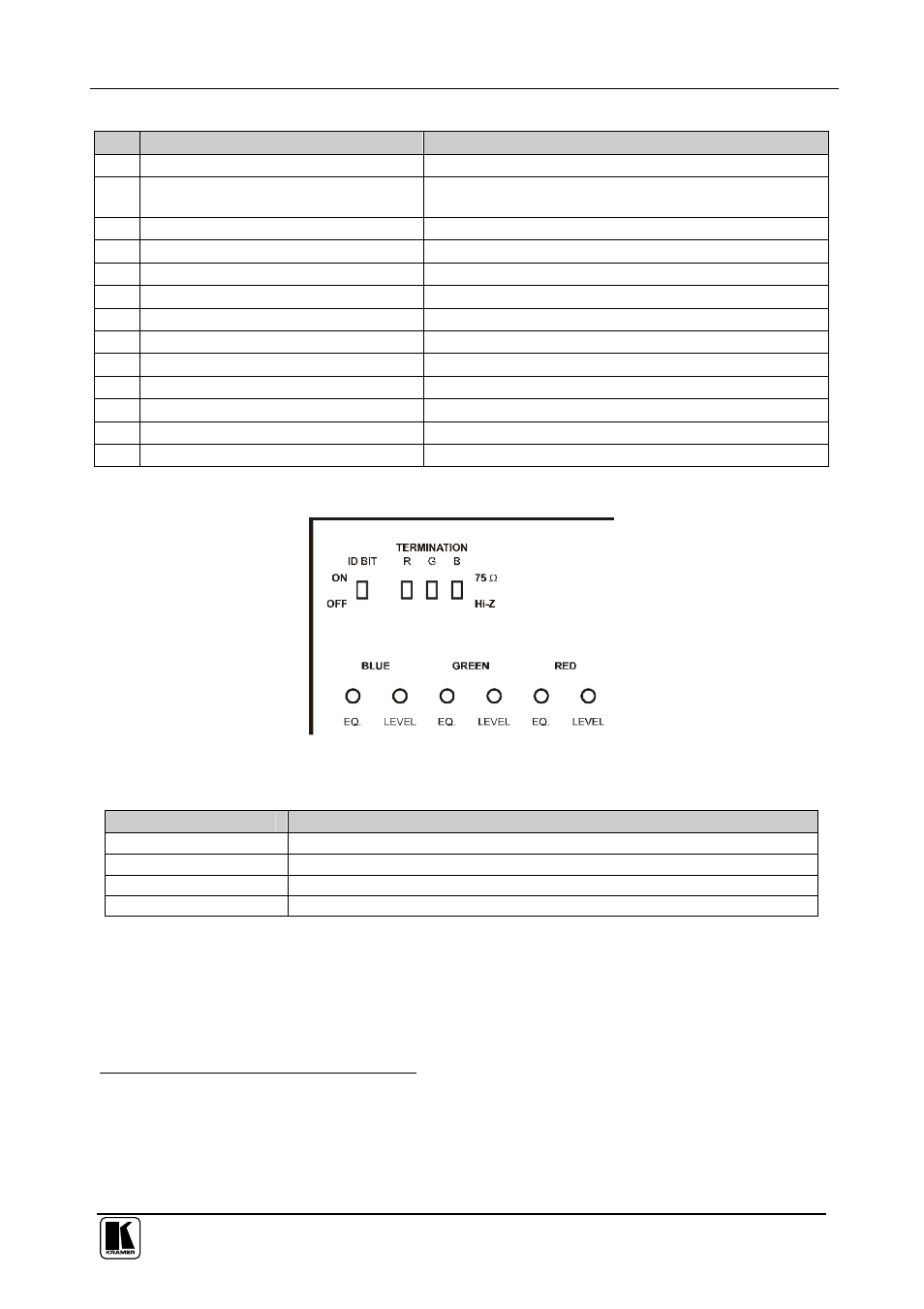
Figure 2 and Table 2 define the underside controls:
Figure 2: VP-108 Underside
Table 2: VP-108 Underside Features
Feature
Function
ID BIT
Switch
Set to ON position
2
to select the ID BIT
3
TERMINATION
4
Switch
Set to ON position
2
to terminate with 75 , or move to Hi-Z for looping
EQ
.
4
Trimmers
Adjust
1
the cable compensation equalization levels for blue, green and red
LEVEL
4
Trimmers
Adjust
1
the output signal levels for blue, green and red
1 Insert a screwdriver into the small hole and carefully rotate it
2 The factory default
3 Sometimes notebook computers refuse to output a VGA signal to an external VGA monitor if they do not detect the ID BIT
as ON. Set the ID BIT to ON using this switch so that the notebook will output to an external VGA monitor
4 Separately for Blue (B), Green (G) and Red (R)