Kramer Electronics VM-50CA User Manual
Page 7
Your VM-50CA 1:5 Video Component / Audio Distributor
5
Table 1: VM-50CA 1:5 Video Component / Audio Distributor Features
#
Feature
Function
1
POWER Switch
Illuminated switch for turning the unit ON or OFF
2
Y RCA Connectors
3
Pb/Cb RCA Connectors Connect to the component video acceptors (from OUT 1 to OUT 5)
4
O
U
T
Pr/Cr RCA Connectors
5
Y RCA Connector
6
Pb/Cb RCA Connector Connect to the component video source
7
IN
P
U
T
Pr/Cr RCA Connector
8
LEFT
Adjust
1
the left audio signal output level
9
LEVEL
Trimmer
RIGHT
Adjust the right audio signal output level
10
R
Connect to the right analog audio source
11
INPUT RCA
Connector L
Connect to the left analog audio source
12
R
Connect to the right analog audio acceptors (from OUT 1 to OUT 5)
13
A
N
A
LO
G
A
U
D
IO
OUT RCA
Connectors L
Connect to the left analog audio acceptors (from OUT 1 to OUT 5)
14
INPUT
Connect to the digital audio source
15
S/PDIF RCA
Connectors
OUT
Connect to the digital audio acceptors (from OUT 1 to OUT 5)
16
Power Connector with Fuse AC connector enabling power supply to the unit
The
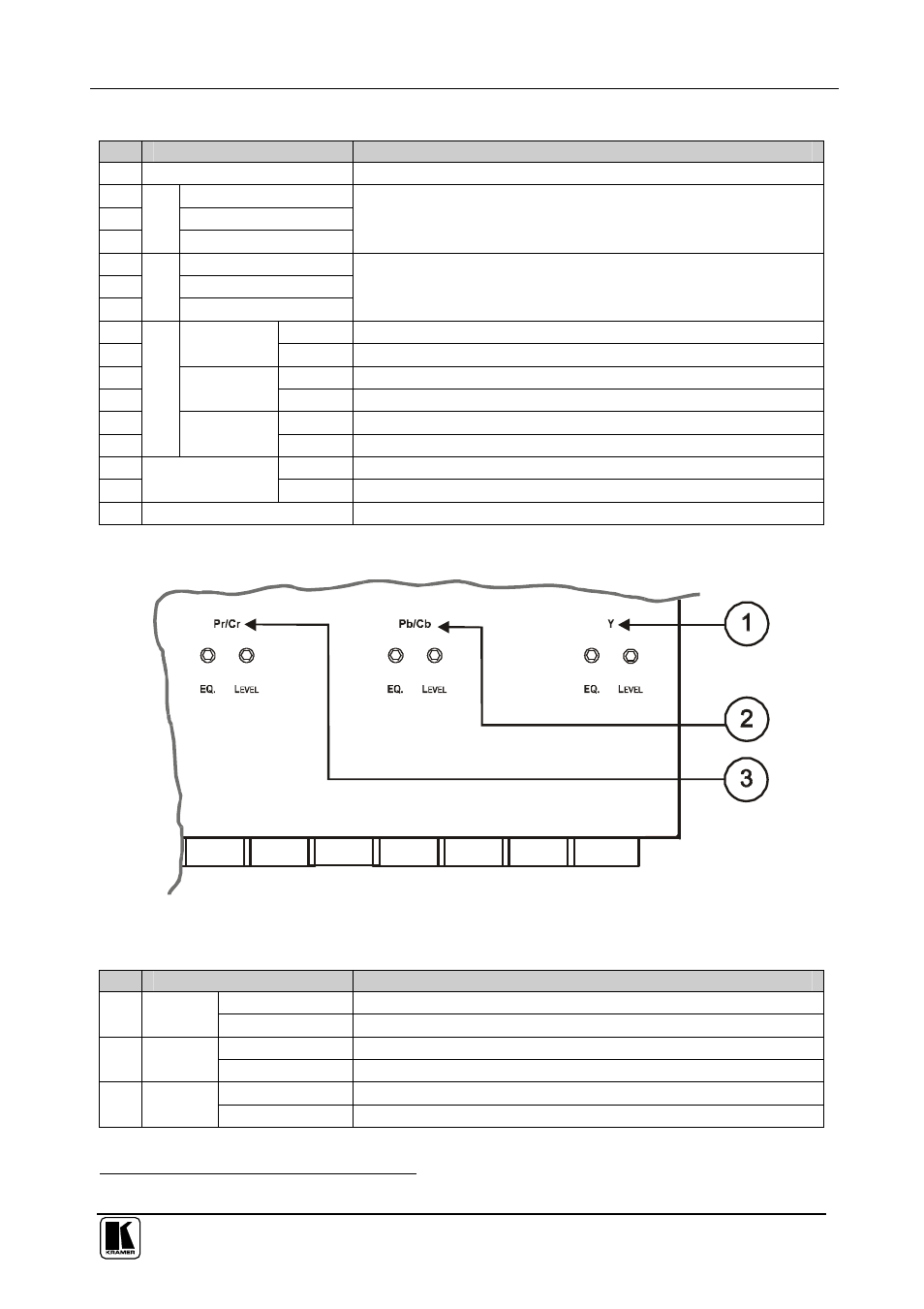
VM-50CA underside is illustrated in Figure 2 and defined in Table 2:
Figure 2: VM-50CA Underside View
Table 2: VM-50CA Underside View Features
#
Feature
Function
1
EQ. Trimmer
Adjust
1
the Y cable compensation equalization level
Y
LEVEL Trimmer
Adjust
1
the Y output signal level
2
EQ. Trimmer
Adjust
1
the Pb/Cb cable compensation equalization level
Pb/Cb
LEVEL Trimmer
Adjust
1
the Pb/Cb output signal level
3
EQ. Trimmer
Adjust
1
the Pr/Cr cable compensation equalization level
Pr/Cr
LEVEL Trimmer
Adjust
1
the Pr/Cr output signal level
1 Insert a screwdriver into the small hole and carefully rotate it, to trim the appropriate level