Installation directions, Prepare strike, Prepare frame – HES 9400 User Manual
Page 2: Finish installing
2
Installation Directions
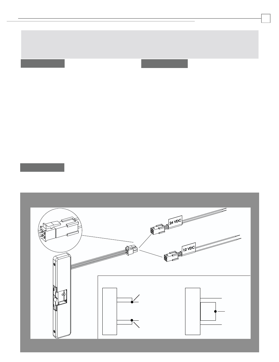
1. Select the appropriate Plug In Connector that
matches system power and electrically connect as
illustrated in Diagram 2. For 12V DC, the pigtail
marked “12 VDC” should be used. For 24V DC, the
pigtail marked “24 VDC” should be used. If no
connector is present, configure the wires as illus-
trated within Diagram 2.
2. If using the Latchbolt Monitor (LBM) or Latchbolt
Strike Monitor (LBSM), refer to Diagram 3 & 4 on
page 3 to complete wiring.
3. The 9400 ships in the Fail Secure mode of opera-
tion. If you need to convert to Fail Safe Operation
see Diagram 5 on page 3.
Prepare Strike
CAUTION! Before connecting any device at the installation site, verify input voltage using a multimeter.
Many power supplies and low voltage transformers operate at higher levels than listed. Any input voltage exceeding
10% of the solenoid rating may cause severe damage to the unit and will void the warranty.
Prepare Frame
4. Prepare the door jamb using the Installation
Template located on page 4 (with the exception of
the hole for final lockdown).
Finish Installing
RED
RED/GREEN
BLACK
VIOLET
RED
BLACK
VIOLET
RED/GREEN
IF CONNECTOR IS MISSING
DIAGRAM 2: 12V to 24V CONVERSION
(+ 12 VDC)
(-NEG)
(+ 24 VDC)
(-NEG)
or
ELECTRIC STRIKE
ELECTRIC STRIKE
CONNECT
TOGETHER
CONNECT
TOGETHER
CONNECT
TOGETHER
5. Electrically connect the 9400 to the Plug In Con-
nector, and attach the electric strike to the jamb
using the 1/4”-20 cap screws provided.
6. Check latchbolt interaction to determine if
horizontal adjustment is needed, and adjust as
needed. Lockdown horizontal adjustment using the
#10-32 setscrews as illustrated on page 4.
7. OPTIONAL LOCKDOWN FEATURE: Install the
#10-24 UNC or 10-32 UNF lockdown screw if addi-
tional security is required. Remove the strike
before drilling hole.
8. Install the cover plate, and fix in place using the
#6-32 x 1/4” Cover Screws as illustrated on page 4.