Installation diagrams, Diagram 5: fail safe conversion, Diagram 6: horizontal adjustment – HES 5200 User Manual
Page 3
Installation Diagrams
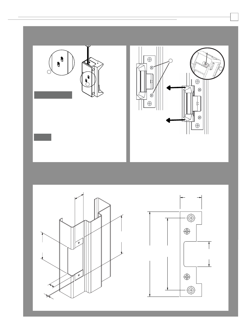
DIAGRAM 7: JAMB CUTOUT DIMENSIONS
DIAGRAM 6: JAMB VIEW
3
DIAGRAM 5: FAIL SAFE CONVERSION
a. Loosen the two #2-56 screws located on the back of the
strike as shown above, but do not remove them.
b. Move screws to the fail safe position as shown above.
c. Tighten screws.
Convert Mode
d. Verify the strike is now in the Fail Safe operation
mode. If the strike still operates as Fail Secure, be
sure screws are fully seated in the bottom
position.
Verify
4-7/8” x 1-1/4” Square Corner Faceplate
ANSI Metal Jamb Installations
5200 with 501 Faceplate
3 -3/8"
[85.7]
1 -1/4"
[31.8]
4 -7/8"
[124]
13/16"
[20.6]
[2.3]
3/32"
[mm]
Inches
1 -1/4"
[31.8]
4 -7/8"
[124]
4 -1/8"
[104.8]
1 -7/16"
[36.6]
a
b
a. Slowly turn the horizontal adjustment screws to adjust the strike
in-frame. Do not remove the screws or completely rotate them
more than 3 full turns.
b. Once the strike has been adjusted, securely tighten the screws.
This will allow the K-nut’s teeth to dig into the strike housing to
prevent slippage during use.
K-NUT
a
b
DIAGRAM 6: HORIZONTAL ADJUSTMENT
Fail Safe