Performance chart – pumps with teflon diaphragms – Graymills DDP .375' Pump User Manual
Page 13
29
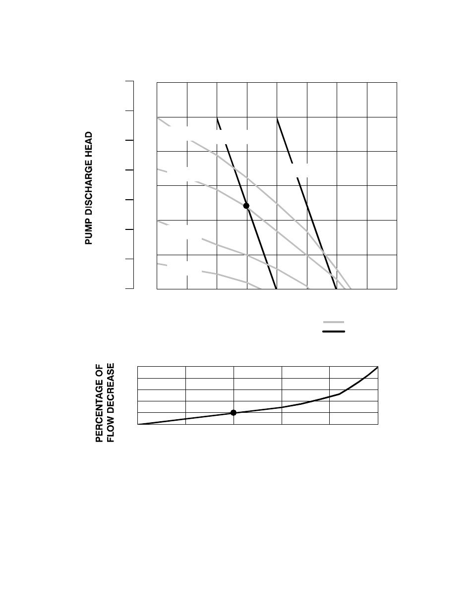
Performance Chart – pumps with Teflon Diaphragms
0
20
40
60
80
100
120
0
1
2
3
4
5
6
7
8
TEST CONDITIONS
Pump tested in water with inlet submerged.
(7.6)
(15.2)
(22.7)
(30.3)
(2.8)
(1.4)
(4.2)
KEY
FLUID PRESSURE AND FLOW
SCFM AIR CONSUMPTION
100 psi air
(7 bar)
Example of Finding Pump Air Consumption and Air Pressure at a Specific Fluid Deliv-
ery and Discharge Head: To supply 3 gpm (11.4 liters) fluid flow (horizontal scale) at 50 psi
(3.5 bar) discharge head pressure (vertical scale) requires 3 scfm (.084 m
#
/min) air con-
sumption at 70 psi (4.9 bar) inlet air pressure.
FLUID FLOW GPM (lpm)
70 psi air
(4.9 bar)
40 psi air
(2.8 bar)
5 scfm
(0.14 m
#
/min)
psi
(bar)
feet
(meters)
280
(85.3)
240
(73.2)
200
(61.0)
160
(48.8)
120
(36.6)
80
(24.4)
40
(12.2)
0
0
20
40
60
80
100
0
5
10
15
20
25
PUMPING RATE DECREASE AT DIFFERENT SUCTION LIFTS
SUCTION LIFT IN FEET (METERS)
(1.52)
(3.05)
(4.57)
(6.1)
(7.62)
EXAMPLE: At a suction lift of 10 ft (3.05 m), the pump flow rate will be decreased by 20 percent.
(5.6)
(7.0)
(8.4)
20 psi air
(1.4 bar)
3 scfm
(.084 m
#
/min)
(3.8)
(11.4)
(19.0)
(26.5)