Stationary pipe dock – Dock Edge + Mooring Arms User Manual
Page 2
Stationary Dock Installations:
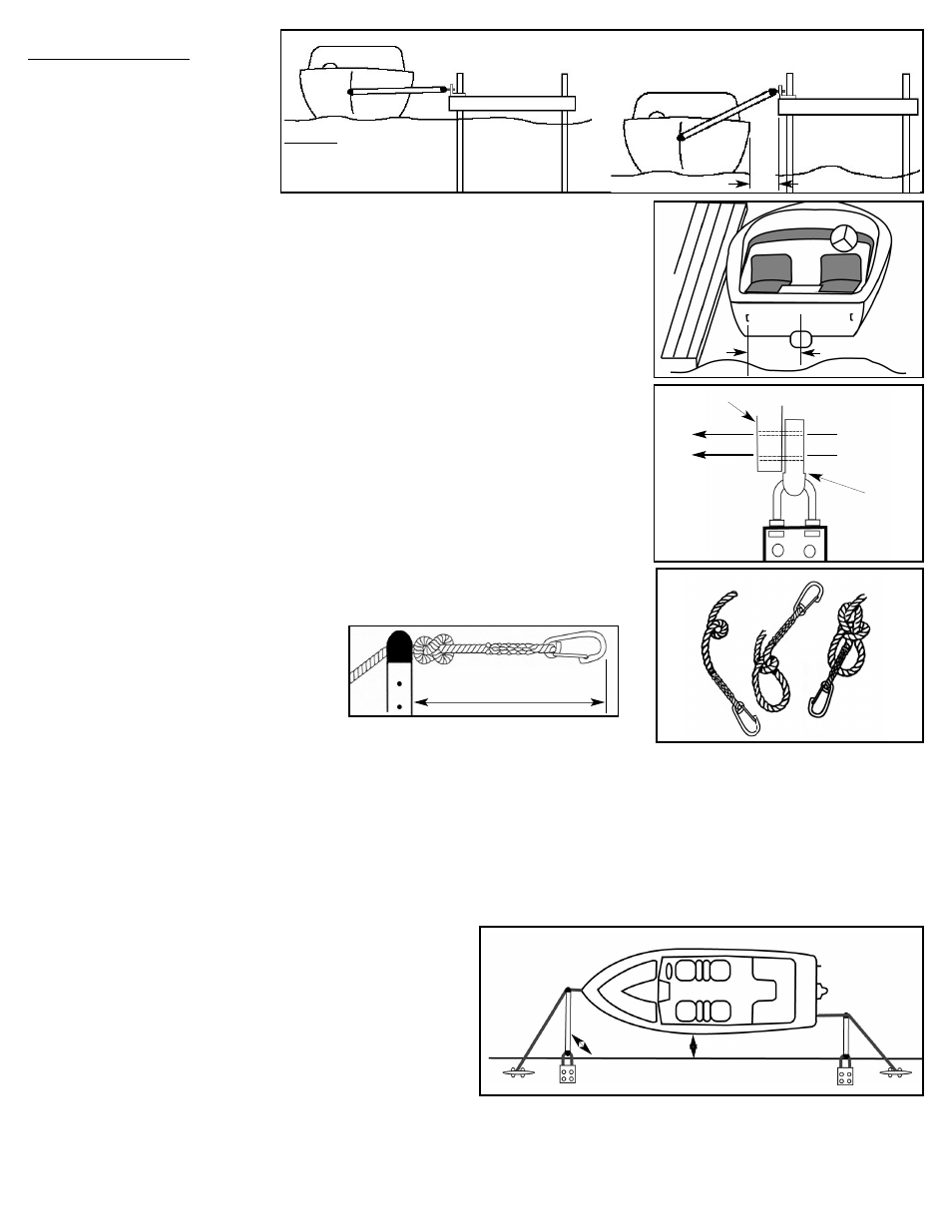
Correctly installed in a stationary dock installa-
tion, the dock will not rise and fall with water level
variations as it does with a floating dock. For this
reason it must be determined what that maximum
change in water level may be. The MINIMUM dis-
tance from dock to boat at either maximum or
minimum water levels should be NO LESS than
12” (31cm).
Note: It may be desirable to shorten one or both mooring arm lengths for one of the following reasons.
1- To keep the boat parallel with the docks edge, example; stern eye is not the center line of the boat
2- To allow the entire boat to be closer to the docks edge yet no closer than 12” (31cm)
3- For use on PWCs or other small craft.
To Shorten a Mooring Arm
1- Measure from the center of the stern to the eye to which the mooring arm WILL be attached, Fig 8. This is the
measurement/ length that must be cut from that mooring arm.
2- Remove the stern arm from the Base Plate by removing the Stainless Steel thru-bolts and lock nuts.
3- Using the measurement from (1), measure from the end without the pole tip and mark that length from the end of
the mooring arm.
4- Using a fine-tooth saw or hack-saw, cut the mooring arm at this location.
5- Using the pole tip as a template Fig. 9, mark and drill new holes in the mooring arm to accommodate the pole tip.
Note: If possible a drill press is preferable to keep the holes in line and on center through the tube.
6- Install the pole tip into the pole, align the holes and reinstall the Stainless Steel screws and lock nuts.
IMPORTANT: If the stern arm has been shortened, it will be necessary to remount the dock cleat for the stern
arm as well to reflect the shorter mooring arm length.
Setting the mooring arms for the boat.
1- Tie a knot in each snap line (J), so that from the knot to the end of the snap clip is 12” (31cm) Fig. 10
2- Thread the free end of the snap line through the mooring arm tip until the knot is stopped at the tip.
3- Align the mooring arm to a 90º angle (right angle) with the docks edge and tie off the snap line onto the cleat for that
mooring arm to retain the 90º angle.
4- Repeat the procedure for the remaining mooring arm.
Using your Mooring Arms
Mooring:
1
Clip the stern snap line onto the stern eyelet
2
Swing the stern mooring arm out until it engages with the knot 12” (31cm) behind the snap clip.
This should place the stern mooring arm at 90º and perpendicular to the docks edge.
3
Clip the bow snap line to the bow eyelet and draw the snap line toward the dock and away from the boat. This will cause the bow mooring arm to slide on the snap line towards
the boat and pull the boat away from the dock until it too engages the knot behind the snap clip.
4
Pull the bow snap line taught and secure to the bow mooring cleat on the dock. This should cause both mooring arms to now be at 90º (right angles) to the dock edge. Fig. 11.
The watercraft is now safely moored and will freely follow water level variations, wakes, waves and tidal movement.
Casting Off: It is only necessary to uncleat one snap line to allow casting off.
1
Uncleat the bow snap line from the dock.
2
Pulling upward on the bow mooring arm will cause the boat to approach the dock.
3
Unsnap the bow snap clip and lay the arm and snap line on the dock for your
return
4
Unsnap the stern snap clip. It is not necessary to uncleat the stern line. Lay the
stern mooring arm and snap line on the dock for reattachment upon your return.
TIPS
To avoid losing snap lines, it’s suggested that a knot be tied in the snap line between the
mooring arm tip(s) and closer to the dock cleat. This will prevent the snap line from slid-
ing through the mooring eye and sinking.
Frequently inspect the mooring arms and components for wear, looseness or damage. Replace components as required.
((FFiigg.. 77))
((FFiigg.. 88))
((FFiigg.. 99))
((FFiigg.. 1100))
((FFiigg.. 1111))
Stationary Pipe Dock
High Water Level
Low Water Level
Measure
DRILL PARALLEL
IMPORTANT: Ensure
holes are parallel to
each other and perpen-
dicular to the pole
when drilling.
Pole Tip
Pole
12”
IMPORTANT
Ensure a MINIMUM clearance of 12”
from watercraft to dock face at low
water levels.
12”
1
2
3
Minimum 12”
90º
Made and Printed in Canada