Dock Edge + Stationary Dock User Manual
How to guide to guide, Stationary dock hardware, How to build a 4’ x 8’ stationary dock
STATIONARY DOCK HARDWARE
HOW
HOW
TO GUIDE
TO GUIDE
USE GREEN LABELLED OR GREEN DOT COMPONENTS
FOR STATIONARY DOCK CONSTRUCTION
LUMBER
Description
QTY
A - Main dock frame
2” x 8” x 96”
2
B - Center truss:
2” x 8” x 92
3/4
”
1
C - End Cap:
2” x 8” x 69”
2
HARDWARE
D - Backer Plate
87-122-F
10
E - Corner Leg Holder
86-100-F
4
F - Hinge Connector*
86-103-F
2
G - Joist Corner
95-122-F
2
H - Washer Plate
99-006-F
4
I - Leg Pipe, 6’8”
93-168-F
4
Hardware Fastener Kit
85-150-F
5
* Required if affixing dock sections or a ramp together.
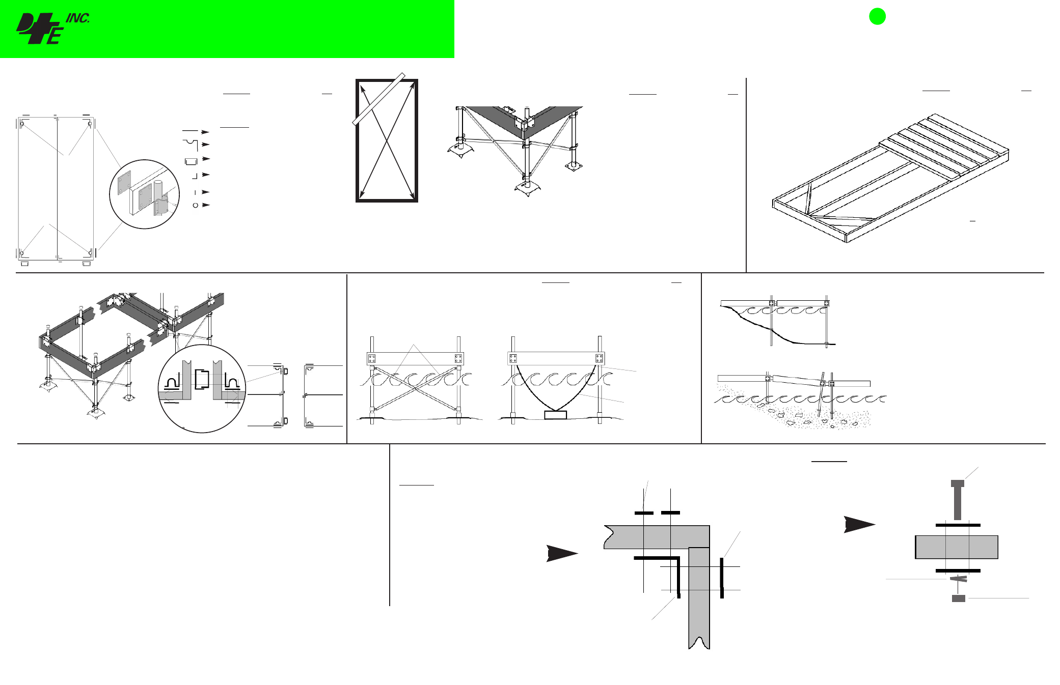
1
Assemble main framework
Drill holes for 87-122-F
HOW TO BUILD A 4’ x 8’ Stationary Dock
Description
QTY
Note: Several options and combinations
available for stabilizing a stationary
dock structure
O - Leg Brace Set
89-101-F
6
M - Corner Leg Brace Holder 87-107-F
4
N - Side Leg Brace holder
93-105-F
4
Q - Bottom Pad
94-102-F
4
or
P - Base Plate
86-102-F
4
2
Reinforcing the leg pipes and choosing a leg
pipe base for bottom conditions
3
A
H
G
G
F
D
D
D
D
D
E
E
E
E
J
A
B
C
C
Assemble decking and connector
hinges. (hinges if attaching to
another dock structure or shore
ramp
SSTTA
ATTIIO
ON
NA
AR
RY
Y D
DO
OC
CK
K
A
AN
NC
CH
HO
OR
RA
AG
GEE
Anchorage
to suit
Description
QTY
S - Chain Retainer
99-013-F
2
H - Washer Plate
99-006-F
4
Galvanized chain:
5/16” x approx
48’
Hardware Fastener Kit
85-150-F
1
Anchorage
Min. 125lb ea.
2
S
S
4
Squaring your Dock Structure
Z
Check the squareness by measuring from corner to
corner of the frame in an “X” pattern as shown. The
measurement should be +/- 1/4” between each other. Lock
the framework into square by temporarily securing a piece
of lumber (Z) across one corner as shown above.
IMPORTANT:
DockEdge+ Inc. assumes no responsibility or liability for the accuracy or representation of the graphic illustrations shown in this hardware guide. These graphic illustrations are not
intended to be architectural drawings, and are not to be substituted for engineered drawings. Each is intended as a guideline ONLY. DockEdge+ Inc. does not warrant the quantities and/ or bill of materials to be
accurate in all uses and applications. Individual dock structures may vary by necessity, preference or design. It may be necessary to vary the amount of materials listed in this guide depending on dock size,
material usage, necessity and/ or the severity of the conditions to which the dock structure is subjected to. All graphic illustrations are based on the use of conventional framework of 2” x 6” lumber and decking
lumber. Freeboard may be adjusted by using 2”x8” or 2”x10” lumber. Substitutions in lumber and hardware placement may effect floatation.
Printed in Canada
020711
-
Electric Drill
-
3/16” drill bit
-
3/8” drill bit or auger
-
3/8” drive Socket wrench set
-
Wrench set
-
#2 Robertson (square) bit drive for decking screws
-
Pencil
-
Measuring tape
-
2-1/2” hole saw (not required if mounting leg pipes on outer dock face)
Tools Required for the average Dock Build
(excludes sizing/ cutting of structural wood members)
NOTE: consideration should be given to the
type of bottom the dock will be resting on.
Bottom Pads, 94-102-F are larger than the
Base Plate 86-102-F and therefore better for
soft or sandy bottoms where the dock structure
requires a more stable footing. Alternatively, if
necessary, the base plate may be fastened to a
concrete slab or footing if for additional
stability or in areas of strong currents or wave
action.
H
H
I
I
H
O
O
O
N
N
P
Q
Q
O
M
M
M
M
Always use a backer plate
87-122-F on both sides of the
framework when attaching leg
pipe holders. Optional side leg
holders 86-101-F shown
Description
QTY
- Decking:
2” x 6” x 72”
16
R - Decking Screws:
#10 x 3”
96
Connecting Dock Sections
When attaching dock sections, leg
braces should always be used on the
leading edge of each dock section for
stability.
Where dock sections are attached, the
outer backer plate 87-122-F used for
the corner leg holder may simply be
replaced by the hinge connector
86-103-F as shown.
IMPORTANT TIPS
Always use washer plates
(99-006-F), backer plate
(87-122-F) or mating hardware
components together.
Framework of the dock
structure should be
sandwiched between hardware
pieces at all joint locations as
shown. (sample only, other
configurations possible)
99-006-F
Washer Plate
Always use a lock
washer with each
carriage bolt usage
to prevent bolts
loosening over
time.
Carriage
Bolt
Nut
• Use hinge 86-103-F between dock
segments.
• Allow leg pipes to protrude below the bottom
pads by approximately 12” so they will
become embedded in the lake bed.
• Adjust leg pipe holders on leg pipes to level
dock segments before tightening.
• Use hinge 86-103-F between dock
segments.
• Allow the dock segment with the highest
drop in elevation to act as a ramp to a
maximum of 15º angle.
• Adjust leg pipe holders on leg pipes to
sufficient contact with lake bed. Tighten leg
holders.
Wood Frame
Lock Washer
87-122-F
Backer Plate
86-104-F
Inside Corner
Wood Frame
UNEVEN SHORELINE INSTALLATION
GRADED SHORELINE INSTALLATION
Backer Plates not
used with hinges
Galvanized Chain
5/16” to 3/8”
Drive leg pipes no less than 12” into lake bed,
24” if dock to be used for a boat mooring.
Leg Braces
Chain Retainer
Shown with optional corner braces added for
extra rigidity.
F
D
D
E
E
F
®