RMS Technologies IMDE17 INTEGRATED MOTOR + DRIVER + ENCODER User Manual
Page 12
RMS Technologies
Page 12
Version 1.04
IMD17/IMDE17
10/1/2007
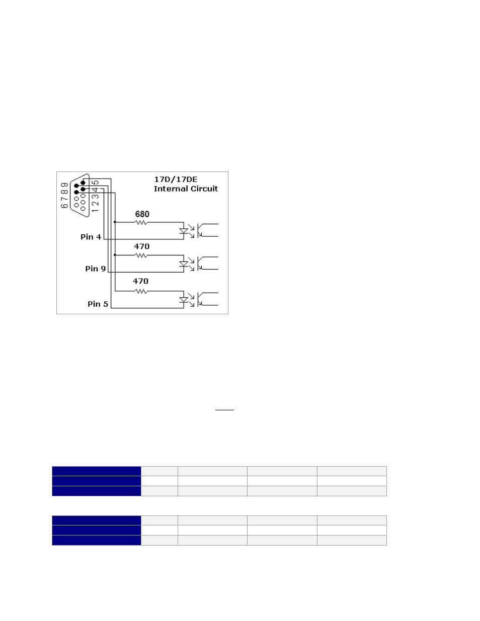
INTERNAL SCHEMATIC
The IMD17 has 3 optically isolated logic inputs. These inputs are isolated to minimize or
eliminate electrical noise coupled onto the drive control signals. Each input is internally
pulled-up to the level of the optocoupler supply and may be connected to sinking outputs on
a controller or a PLC. These inputs are:
Enable/Disable (Pin 4)
Direction (Pin 5)
Step Clock (Pin 9)
Figure 6: Optically Isolated Inputs
Within the Driver lies three 680 Ω
Resistors and three Optocouplers.
The current is limited to 7 mA due to
these three Opto Couplers.
Resistor Values for the Opto Supply
The optocouplers must be powered by an external power supply to maintain isolation. The
Opto Supply for the optocouplers can be between +5 to 24 VDC with respect to the signal
input. It is recommended to use a +5 VDC Opto Supply in order to limit the current going
into the optocouplers to 10 mA. However, if the supply is greater than +5 VDC then a
resistor must be connected in series with each signal line to maintain 10 mA of current
running through the optocouplers. Do NOT provide more than 10 mA or damage may
occur to the driver. Refer to Table 7 & 8 for the corresponding Resistor Values.
The Resistors shall be connected in series with each Input: Pin 4 (Disable), Pin 5 (Direction), and Pin 9
(Step).
Step & Direction lines have a 470 ohm internal resistor
Voltage:
5V
10V
15V
24V
Ohms needed:
0 500 1000 2000
Wattage rating:
0
¼ watt
¼ watt
½ watt
Disable line has a 680 ohm internal resistor
Voltage:
5V
10V
15V
24V
Ohms needed:
0 750 1500 2700
Wattage rating:
0
1/8 watt
¼ watt
½ watt
Table 7 & 8: Resistor Values for inputs