Comfort-Aire AFM42-60 User Manual
Page 8
8
Multi-Position Air Handler with Hydronic Heat with X13 Motor
HWCGxxX0A
Heat Controller
8) Adjust the water heater thermostat so that the water
temperature entering the hot water coils is 120 –
180ºF depending on the amount of heat required by
the structure. This is done with the unit energized
and operating long enough for all temperatures to
stabalize.
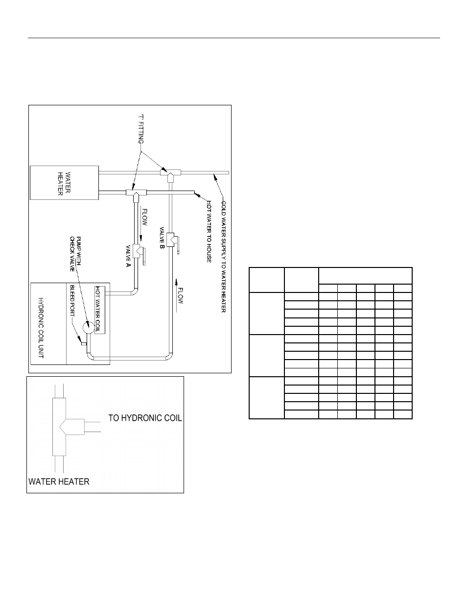
Note: Massachusetts applicable diagram at end of manual
Fig.11. Schematic of hydronic unit set up and typical “T”
installation
After all connections are made, start-up and check-up
must be performed before proper evaluation of the entire
system can be made. Make sure that heat anticipator is
properly set as noted on thermostat instructions.
Load requirements can vary in each residence and it
may be necessary for the installer or homeowner to
make slight adjustments to the heat anticipator setting
for longer or shorter cycles. It is recommended to
change the setting no more than plus or minus 0.05
amps at a time. Greater changes can cause the unit to
rapid cycle or remain on excessively. To properly check
the unit's operation, the installer should have an
electrical current measuring device (0-10 amp Amprobe,
Fluke), air pressure measuring device (0-1.0 in slope
gauge), and a temperature-measuring device (0-200ºF
thermometer).
Install the Amprobe to measure blower current, the slope
gauge to measure static air pressure at the units and the
temperature device to measure unit supply and return air
temperature. Before taking measurements, be sure that
all registers, grilles and dampers are open or set to their
proper positions. Be sure that clean filters are in place.
Temperature measuring device must be installed to
obtain average temperature at both inlet and outlet. For
outlet, measure temperature of each main trunk at a
location far enough away to avoid heater radiation and
read the average temperatures. Table 1 below shows
the CFM that should be achieved at various external
static pressures
0.10 0.20 0.30 0.40 0.50
Tap 5
900 853 797 738 673
Tap 4
670 646 613 592 553
Tap 3
500 476 452 421 400
Tap 2
900 853 797 738 673
Tap 1
400 381 360 339 312
Tap 5
1150 1087 1030 975 910
Tap 4
1080 1048 1010 960 895
Tap 3
900 862 825 796 745
Tap 2
700 663 632 600 552
Tap 1
500 473 449 421 395
Tap 5
1850 1806 1752 1700 1652
Tap 4
1704 1656 1600 1532 1479
Tap 3
1494 1461 1426 1400 1364
Tap 2
1350 1310 1272 1229 1175
Tap 1
676 652 621 600 559
CFM V. External Static
Pressure
AFM18-24
AFM30-36
AFM42-60
SPEED
TAP
MODEL
Table 1. CFM delivered at various external statics
Electric Heat Controls
•
Turn on power supply. Set thermostat fan switch to
on. Set the cooling indicator to maximum, heating to
minimum. System switch may be on heat or cool.
Check slope gauge measurement against
appropriate air flow chart. Make damper, register
and motor speed adjustments to obtain required
airflow.
•
Set thermostat fan switch to auto, system to heat
and thermostat heating indicator to maximum heat.
Blower should start and all heat be energized.
•
Check air flow using temperature rise method.
HWCG48/60X0A
HWCG36/42X0A
HWCG24X0A