Comfort-Aire AFM42-60 User Manual
Page 2
2
Multi-Position Air Handler with Hydronic Heat with X13 Motor
HWCGxxX0A
Heat Controller
Safety Instruction
Potential safety hazards are alerted using
symbol.
The symbol is used in conjunction with terms that
indicate the intensity of the hazard.
WARNING
This symbol indicates a potentially
hazardous situation which if not avoided,
could result in
serious injury, property damage, product damage or
death.
CAUTION
This symbol indicates a potentially
hazardous situation which if not avoided,
may result in
moderate injury or property damage.
WARNING
Certified technicians or those
individuals meeting the requirements specified by
NATE may use this information. Property and
product damage or personal injury hazard may
occur without such background.
WARNING
All power sources should be
disconnected prior to servicing. Failure to do so may
cause personal injury or property damage.
WARNING
Product designed and manufact-
ured to permit installation in accordance with local and
national building codes. It is the installer’s responsibility
to ensure that product is installed in strict compliance
with national and local codes. Manufacturer takes no
responsibility for damage (personal, product or property)
caused due to installations violating regulations. In
absence of local/state codes, refer to
National Electric
Code: NFPA 90A & 90B Uniform Mechanical Code
(CEC or CSA for Canadian Installation).
WARNING
When this unit is installed in an
enclosed area, such as a garage or utility room with any
Carbon Monoxide producing devices (i.e. automobile,
space heater, water heater etc.) ensure that the
enclosed area is properly ventilated.
CAUTION
Only factory authorized kits and
accessories should be used when installing or modifying
this unit unless it is so noted in these instructions. Some
localities may require a licensed installer/service
personnel.
WARNING
Unit is not approved for outdoor
installations.
WARNING
The unit is designed for operation
with 108/120 V, single phase, 60 Hz power supply.
manufacturer will not be reponsible for damages caused
due to modification of the unit to operate with alternative
power sources.
Inspection
On receiving the product, visually inspect it for any major
shipping related damages. Shipping damages are the
carrier’s responsibility. Inspect the product labels to
verify that the model number and options are in
accordance with your order. Manufacturer will not accept
damage claims for incorrectly shipped product.
Installation Preparation
Read all the instructions in this guideline carefully while
paying special attention to the WARNING and CAUTION
alerts. If any of the instructions are unclear; clarify with
certified technicians. Gather all the tools needed for
successful installation of the unit prior to beginning the
installation.
This unit is designed for zero clearance installation on
three sides and adequate clearance to provide access
for serivce in the front. A min of 2.5 – 3.5 feet clearance
is recommended on the front end.
If the unit is to be installed in garages, warehouses or
other areas where they may be subjected to physical
damage, adequate protective barriers must be installed.
Unit
MUST be installed 18” away from source of ignition.
If the unit is located in high humidity areas like attics or
unconditioned garage; the air handler casing might
experience nuisance sweating. In such installation
scenarios, wrapping the casing with a 2” fiberglass
insulation with vapor barrier
SHOULD be used.
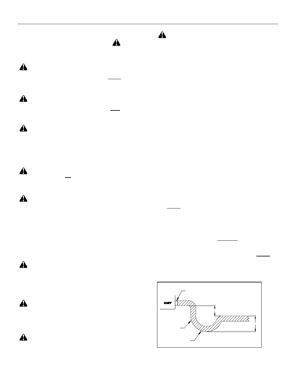
The drain lines must be installed with ¼” per foot pitch to
provide free drainage. A condensate trap
MUST be
installed on the primary drain line to ensure proper
drainage of the condensate. The trap must be installed
in the drain line below the bottom of the drain pan.
Figure 1 illustrates the typical drain trap installation
2" MINIMUM
3" MINIMU
FLEXIBLE
TUBING-HOSE
OR PIPE
A POSITIVE
LIQUID SEAL IS
REQUIRED
DRAIN
CONNECTION
Figure.1. Typical drain line trap set up