Caution, Field – installed expansion valve coils, Warning – Comfort-Aire AFM42-60 User Manual
Page 4
4
Multi-Position Air Handler with Hydronic Heat with X13 Motor
HWCGxxX0A
Heat Controller
Fig. 2 shows the recommended position for the TXV bulb
installation in the horizontal plane.
The TXV sensing bulb
SHOULD be mounted using the
metal clamp provided. In order to obtain a good
temperature reading and correct superheat control, the
TXV sensing bulb must conform to ALL of the following
criteria:
1) The sensing bulb must be in direct and
continous contact with the suction line
2) The sensing bulb should be mounted
horizontally on the suction line.
3) The sensing bulb must be mounted above and
between the 4 and 8 o’clock position on the
circumference of the suction line.
4) The sensing bulb must be insulated from outside
air.
TXV BULB POSITION
4 O'CLOCK OR
8 O'CLOCK
METAL STRAP
SUCTION/VAPOR LINE
Fig.2. Recommended location of the TXV bulb in a
horizontal orientation
The mounting location and insulation guards the sensing
bulb from false reading due to hot outside air or liquid
refrigerant formed inside the suction/vapor line.
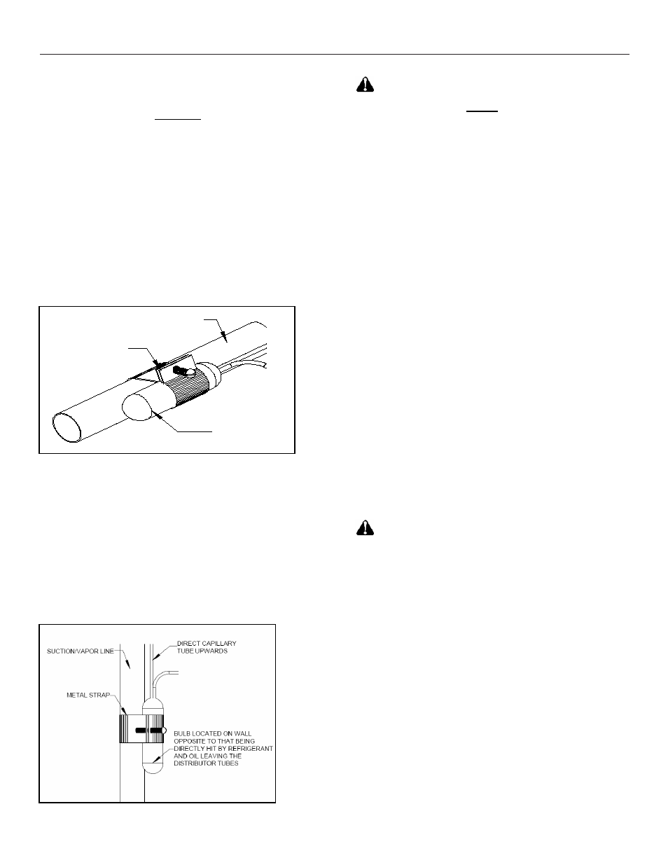
As recommended earlier, the TXV sensing bulb should
be mounted in a horizontal plane in relation to the
suction/vapor line. However, in case such a mounting is
not feasible and the sensing bulb has to be mounted
vertically; then place the bulb as shown in Fig.3.
Fig.3. Sensing bulb mounted in a vertical orientation
CAUTION
If the TXV sensing bulb is mounted
vertically; the capillary
MUST be directed upwards. The
bulb must be mounted on the wall opposite to that being
directly hit by the refrigerant and oil leaving the
distributor tubes.
Field – Installed Expansion Valve Coils
Remove the valve identification sticker from the valve
and place it adjacent to the model number on unit name
plate.
When installing an expansion valve, it is not necessary
to remove all the access panels and slide the coil out of
the housing.
1) Disassemble the flowrator body using two
wrenches. Unscrew the body with a counter-
clockwise motion.
2) Replace the white Teflon seal in place (located
between the halves).
3) Remove the existing flowrator piston using a
small wire or pick.
4) Inspect the TXV box to confirm that the valve is
compatible with the refrigerant in the system.
5) Remove the valve from the box and note the
location of the inlet side (threaded male port)
and the outlet side (female swivel nut port).
6) After ensuring that the white Teflon seal is still in
place inside the flowrator body, screw the
female swivel nut onto the flowrator body.
7) Place the attachment nut on the liquid line.
8)
Braze the stub-out portion to the liquid line and
let cool.
WARNING
Do not attempt to touch the braze
joint while hot. Touching it may cause sever burns.
9) Remove the additional white Teflon seal ring
from the box and place on the shoulder just
inside the inlet port. Screw the nut attached to
the stub-out portion of the flowrator body onto
the inlet port of the TXV.
10) Tighten all connections taking care to use proper
back up.
Some coils come with a Schrader valve on the suction
line. If a Schrader port is present
11) Remove valve stem from the Schrader port
mounted on the suction line
12) Screw flare nut on TXV equalization tube in to
the Schrader valve stem
Coils without Schrader Ports
11) Locate a convenient spot on the suction line
and punch a ¼” hole with a pick or other suitable
tool.