Warning – Comfort-Aire HMB**V*1E SERIES User Manual
Page 9
9
Circuit Brea
ker
Cover
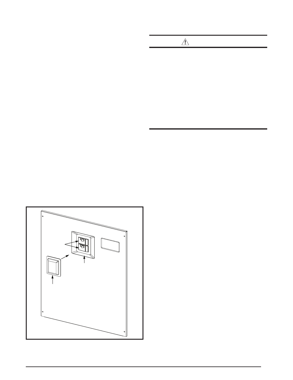
Circuit
Breakers
Recess
Air Handler A
ccess Door
Figure 6. Circuit Breaker Cover
Circuit Breaker Cover Installation
The air handler circuit breaker cover is designed to protect
the breakers of an installed heater kit from debris and
condensation.The cover attaches to the breaker recess
of the air handler upper access door using a double-sided
adhesive gasket. See Figure 6. The heater kit circuit
breaker toggles are still accessible and can be switched
with the cover in place.
There are 2 different circuit breaker cover sizes:
• 2-breaker cover for 2, 2.5, 3, & 3.5 ton air handlers.
• 3-breaker cover for 4 & 5 ton air handlers.
After the heater kit is properly installed, remove the
appropriate knockouts in the upper air handler access door
and follow these instructions to install the breaker cover:
1. Clean any oil, dirt, or insulation fibers from the recess
area of the air handler access door. This step is important
for ensuring the gasket adheres properly to the sheet
metal door.
2. Remove release paper from one side of the gasket
and attach to back side of the breaker cover.
NOTE: For proper alignment, It is recommended to leave
the center section of the gasket in place when attaching
the gasket to the breaker cover. Remove the center
section after the gasket is applied to the breaker cover.
3. Remove the release paper from the other side of the
gasket and attach to the circuit breaker recess area.
4. Press firmly along all four sides of the cover to ensure
gasket and cover are securely attached to the access
door.
ELECTRICAL CONNECTIONS
WARNING:
ELECTRICAL SHOCK, FIRE OR EXPLOSION
HAZARD
Failure to follow safety warnings exactly could
result in serious injury or property damage.
Improper servicing could result in dangerous
operation, serious injury, death or property
damage.
• Before servicing, disconnect all electrical power
to the air handler.
• When servicing controls, label all wires prior
to disconnecting. Reconnect wires correctly.
• Verify proper operation after servicing.
• Electrical connections must be in compliance with
all applicable local codes and ordinances, and with
the current revision of the National Electric Code
(ANSI/NFPA 70).
• For Canadian installations, the electrical connections
and grounding shall comply with the current Canadian
Electrical Code (CSA C22.1 and/or local codes).
Pre-Electrical Checklist
√ Verify the voltage, frequency, and phase of the supply
source match the specifications on the unit rating plate.
√ Verify that the service provided by the utility is sufficient
to handle the additional load imposed by this equipment.
See the unit wiring label or Table 9 (page 21) for proper
high and low voltage wiring.
√ Verify factory wiring is in accordance with the unit wiring
diagram (Figures 15 - 17, pages 25 - 27). Verify none of
the connections loosened during shipping or installation.
Line Voltage
•
An electrical disconnect must be located within sight
of and readily accessible to the unit. This switch shall
be capable of electrically de-energizing the outdoor unit.
See unit data label for proper incoming field wiring. Any
other wiring methods must be acceptable to authority
having jurisdiction.
• It is recommended that the line voltage to the unit be
supplied from a dedicated branch circuit containing the
correct fuse or circuit breaker for the unit.
• Overcurrent protection must be provided at the branch
circuit distribution panel and sized as shown on the unit
rating label and according to applicable local codes. See
the unit rating plate and Table 9 (page 21) for maximum
circuit ampacity and maximum overcurrent protection
limits.
• The installer should become familiar with the wiring
diagram/schematic before making any electrical
connections to the unit. See the unit wiring label or
Figures 15 - 17.
• Use only copper wire for the line voltage power supply
to this unit. Use proper code agency listed conduit and