Comfort-Aire HMB**V*1E SERIES User Manual
Page 7
7
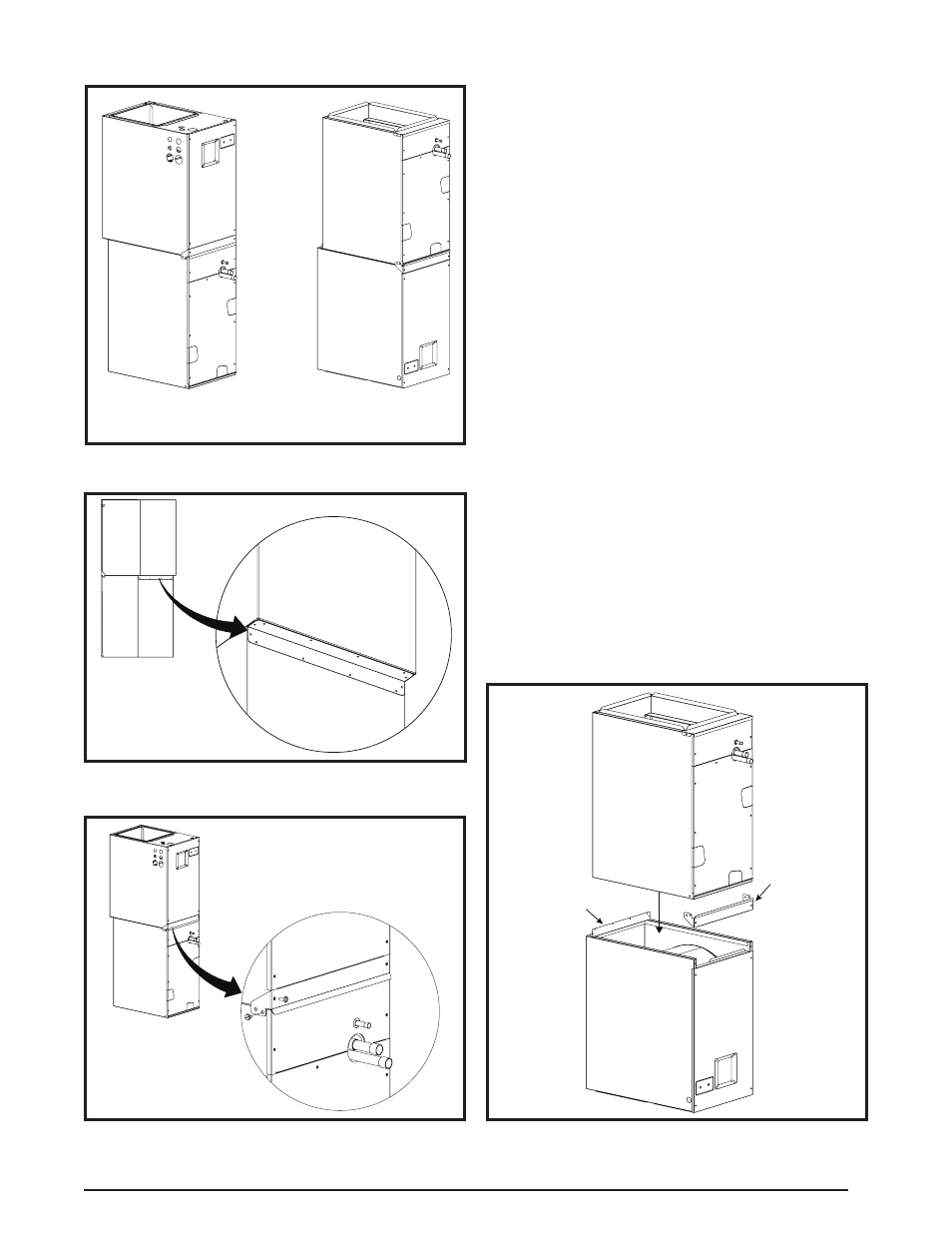
Figure 1. Upflow & Downflow Installation
Upflow
Configuration
Downflow
Configuration
Figure 3. Front Bracket Installation - (Upflow Only)
Front Bra
cket
Figure 2. Rear Bracket Installation - (Upflow Only)
Rear Bra
cket
Modular Air Handler
Cased Coil
Upflow
Configuration
Downflow Installation
The HMB Series Modular air handler may be installed in
a downflow configuration as shown in Figure 1. Return
air must enter through the top of the unit.
1. Remove the lower front bracket (Figure 3) from the
modular unit. Retain the screws for later use.
2. Remove the door from the cased coil and the screws
(on the side of the cased coil) securing the lower tie bar
in place. Retain the screws for later use.
NOTE: Before
mating the modular unit with the cased coil, clean the
mating surfaces on both units.
3. Flip the modular unit upside down and apply the black
neoprene gasket tape to the top of the air handler.
NOTE: The blowers flanged surface is now beneath the
air handler and will connect with the supply air duct.
4. Carefully place the cased coil on top of the modular
air handler.
NOTE: Make sure the units are flush in the
front and on the sides with a “step” fit in the back and
that there are no gaps on the sides. See Figure 4.
5. Attach the front joining bracket to the cased coil and
the air handler. Align the screw holes in the bracket with
the holes where the lower front bracket and lower tie
bar were attached.
6. Secure the bracket to the modular unit and the cased
coil with the screws removed earlier in steps 1 & 2.
7. Attach the rear joining bracket to the backside of the
modular unit. Position the bracket so that it is flush with
the sides and back of the units with the 1/2” insulation
facing the rear gap between the units.
8. Secure the rear bracket to the modular unit and cased
coil with self-tapping screws.
Figure 4. Downflow Brackets
Rear
Bracket
Front
Bracket
Cased
Coil
Modular
Air Handler