Pag e 4 – Australian Monitor AMISCL2 User Manual
Page 4
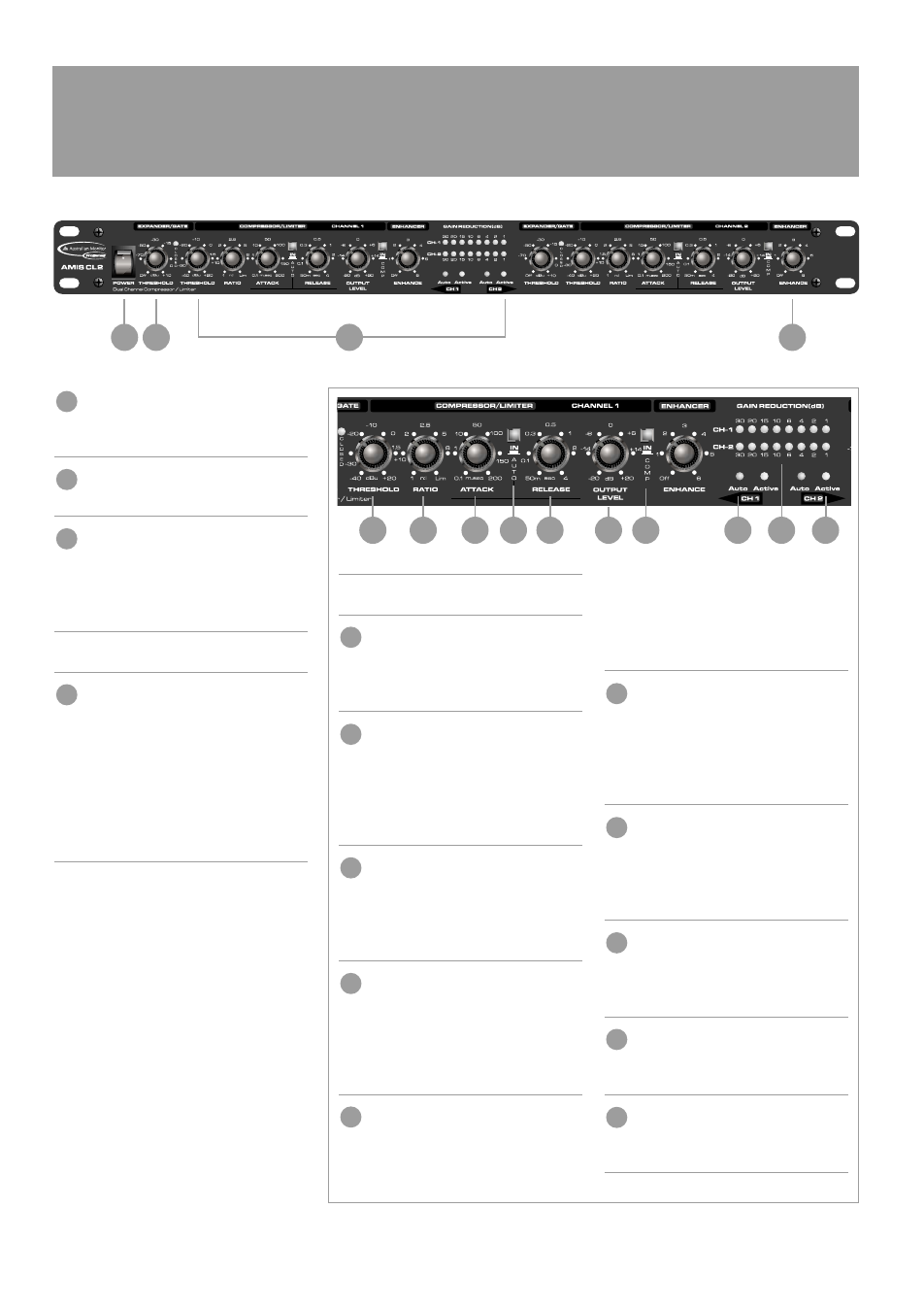
P OW E R S W I T C H
This switches the mains power "on"
to the unit.
C O M P R E S S O R / L I M I T E R S E C T I O N
Refer to inset box immediately opposite.
E X PA N D E R / G AT E T H R E S H O L D
This control adjusts the threshold level of
the expander/gate within a range from off
(bypass) to +10dB. The Red LED glows
when expansion occurs.
E N H A N C E R
E N H A N C E M E N T
Dynamic enhancement allows you to
replenish any high frequencies lost
through the compression process, for
natural sounding dynamics control. This
control allows you to vary the amount of
dynamic enhancement added.
Enhancement is only added when
compression is taking place.
PAG E 4
A M I S C L 2 I N S TA L L AT I O N & O P E R AT I O N M A N UA L
F R O N T PA N E L
1
2
3
14
1
3
14
4
5
6
7
8
10
12
13
11
9
C O M P R E S S O R L I M I T E R S E C T I O N
T H R E S H O L D
This controls threshold at which
compression will start to occur.
It has a range from -40 to+20 dBu.
R AT I O
This control determines the compression
ratio between the input and output level
for all signals exceeding the threshold
point. The ratio can be adjusted from 1:1
(unity gain) to infinity:1 (Limiting)
AT TAC K
The attack control determines the speed at
which the compressor will respond to sig-
nals that exceed the threshold. The attack
range is from 0.1 to 200 milliseconds.
R E L E A S E
The Release control determines the
amount of time it will take the compressor
to return to unity gain after signal falls
below the threshold level. This can be
adjusted from 0.05 to 4 seconds.
AU TO I N
The Auto In switch disables the Attack
and Release controls and controls these
parameters automatically from
the program material. This function
allows for unobtrusive musical compres-
sion of signals or mixes with widely
varying dynamics.
O U T P U T L E V E L
This control allows for an increase or
decrease of the output level by up to
20dB, thus allowing the user to compen-
sate for any level loss due to the
compression or limiting process.
I N / O U T S W I T C H
This switch allows the compressor/lim-
iter section to be bypassed. This makes
A/B comparisons between original and
processed material very simple.
G A I N R E D U C T I O N M E T E R
This 8 segment LED meter shows the
actual gain reduction per channel and
has a range from 0 to 30dB.
AU TO L E D
This shows when the “Compressor
Auto” function is active.
AC T I V E L E D
This shows when the compressor/limiter
is switched in.
9
10
11
12
13
4
5
6
7
8
2