Pag e 5 – Australian Monitor IS600 User Manual
Page 5
PAG E 5
I S S E R I E S I N S TA L L AT I O N & O P E R AT I O N M A N UA L
I S S E R I E S I N S TA L L AT I O N & O P E R AT I O N M A N UA L
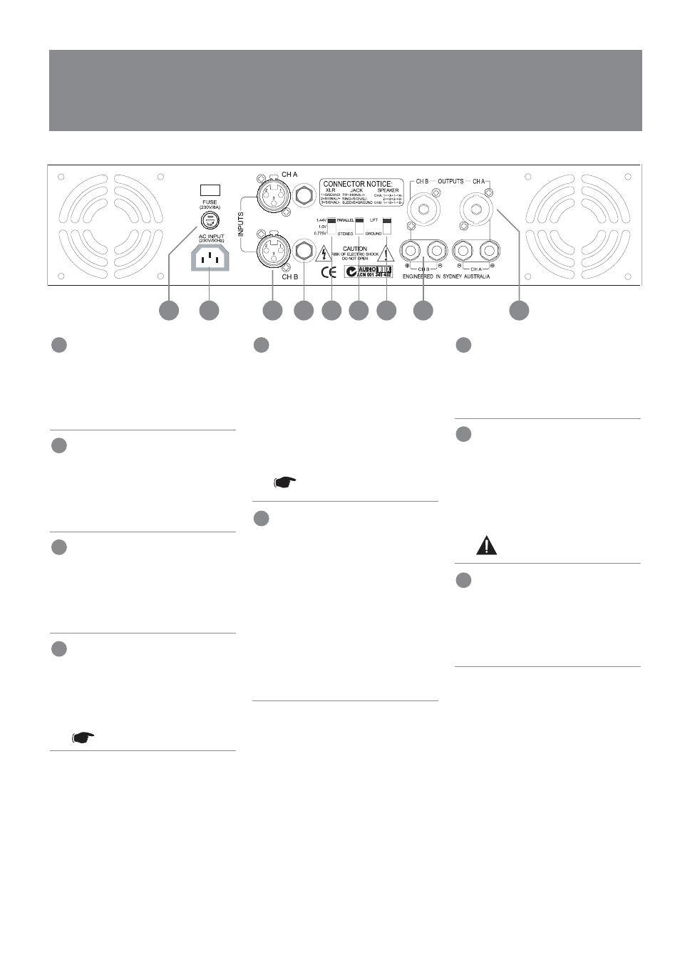
R E A R PA N E L
B A L A N C E D X L R I N P U T
A female 3-pin XLR type connector is
provided for each input:
Pin 1 = Signal Ground;
Pin 2 = Hot (non-inverting or in phase);
Pin 3 = Cold (inverting or reverse phase).
B A L A N C E D 6 . 3 5 M M T R S I N P U T
A female 6.35mm TRS connector is
provided for each input.
Tip = Hot (non-inverting or in phase);
Ring = Cold (inverting or reverse phase);
Sleeve = Signal Ground.
I N P U T S E N S I T I V I T Y S W I T C H
This switch allows the amplifiers input
sensitivity to be correctly matched to
the equipment providing the amplifiers
input signal. See the Operation section
(page 8) for more details.
PA R A L L E L / S T E R E O S W I T C H
This switch determines whether channels
A & B are receiving separate signals
(i.e. Operating in stereo mode) or whether
the input signal from channel A is being
fed through to channel B.
NOTE: This is not Bridge mode.
G R O U N D L I F T S W I T C H
When this switch is engaged, it
disconnects signal ground from the input
connectors on both channels. It is
intended to be used when "hum" is caused
by earth loops (due to different ground
potentials between source equipment and
the amplifier) or stray magnetic field pick
up on the input ground/shield wiring.
The amplifier should be turned off
before engaging this switch!
S P E A K E R O U T P U T C O N N E C TO R
A 4 pole speaker connector is provided
as an additional speaker output.
This standard of loudspeaker-to-amplifier
connection allows access to both
channels of the amplifier via the one
connector for bi-amp applications.
Channel-A is considered the dominant
channel and has both channels wired
to the speaker connector. See the
installation section of this manual
for detailed information on speaker
connector wiring.
M A I N S F U S E
M A I N S C O N N E C T I O N
Your amplifier is fitted with an
internationally recognised IEC mains inlet
connector. Please ensure that the
connecting mains lead for use with the
IEC connector is of an approved type and
is of sufficient current carrying capacity.
NOTE: Your unit must always
be earthed!
B I N D I N G P O S T O U T P U T S
Touch-proof binding posts (banana jacks)
are provided for speaker output
termination with banana plugs or bare
wire. The red post is used as positive and
the black post is used as negative.
14
9
8
10
11
7
11
12
13
14
15
5
1
3
1
12
7
8
9
10
The IS600 is fitted with an 8 amp slow blow
fuse & the IS1200 is fitted with a 15 amp
slow blow fuse. The IS1600 is fitted with
a 15 amp slow blow fuse.