Pag e 4 – Australian Monitor IS600 User Manual
Page 4
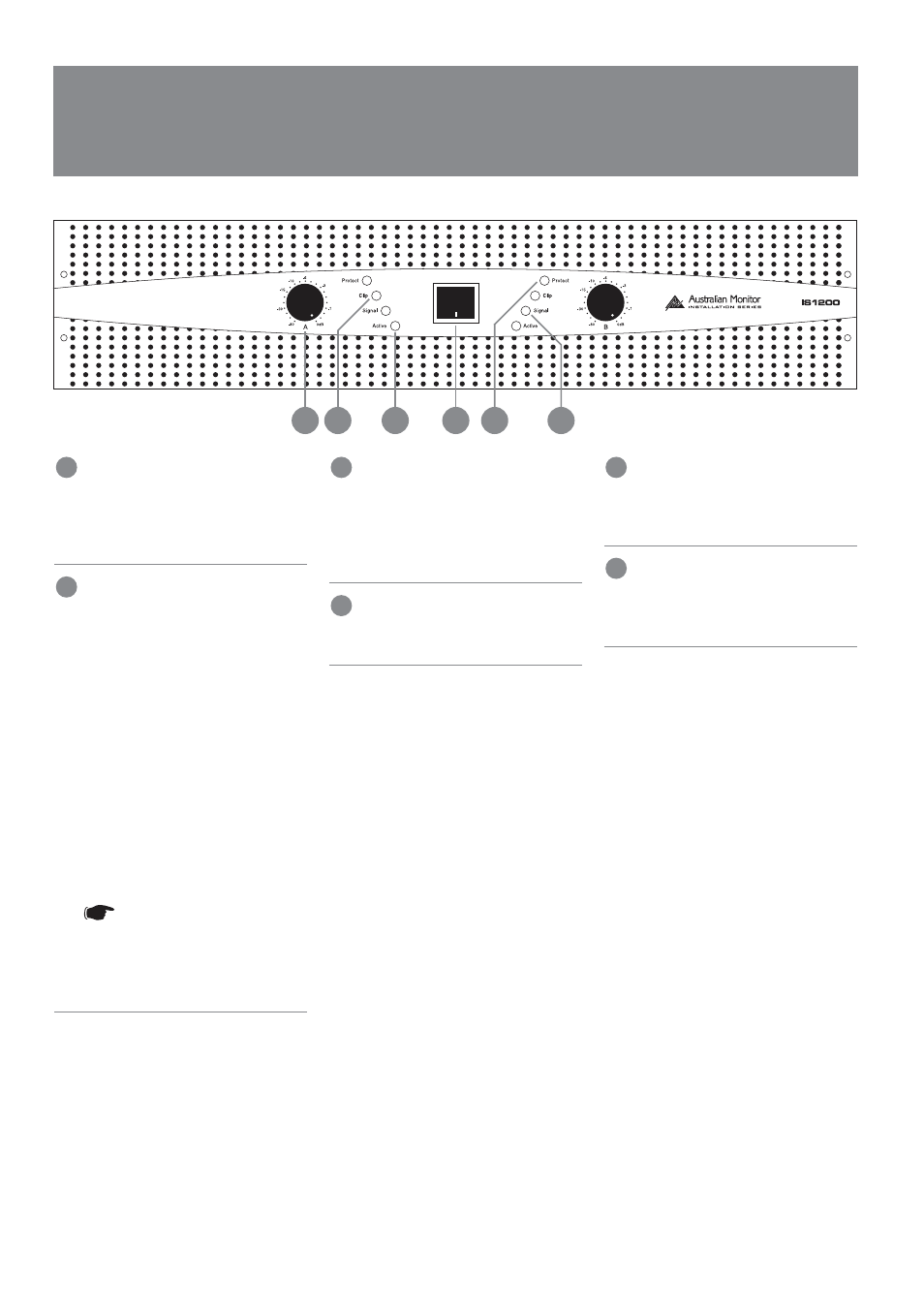
AT T E N UATO R
There are 2 level controls on all IS models.
Each control is labelled for the channel
which it controls. 0dB indicates minimum
attenuation.
C L I P I N D I C ATO R
This LED displays the status of the output
stage and displays two levels of operation.
These levels are:
Below clip level
(unlit)
Clipping & above
(red)
The LED will change to red once the
output exceeds the clipping point of the
amplifier’s output stage. The threshold is
referred to the amplifier supply rails and
alters with changes in the mains supply,
changes in the load and duty cycle
fluctuations.
The attack and decay time (ballistics) of
the status circuit are those of a Peak
Programme Meter (P.P.M.)
NOTE: The amplifier is not
damaged by running into
clipping, but speakers may be.
To maximise the life of
your speakers, try to keep
clipping infrequent.
P OW E R S W I T C H
This switches AC power to the amplifier.
Press the switch to up for power on and
down for power off. At start-up (turn-on),
the input to the amplifier is muted for
approximately two seconds.
P R OT E C T I N D I C ATO R
This red LED will illuminate when thermal
shutdown occurs.
AC T I V E I N D I C ATO R
This LED will illuminate blue and indicates
that the amplifier is ON and receiving AC
mains power.
S I G N A L I N D I C ATO R .
This LED displays the status of the output
stage and varies in intensity in proportion
to the output signal level.
PAG E 4
F R O N T PA N E L
5
3
4
1
2
3
5
4
6
1
2
6
I S S E R I E S I N S TA L L AT I O N & O P E R AT I O N M A N UA L