Iii - engineering data, Appendix iii, Engineering data – Goulds Pumps 3409 - IOM User Manual
Page 59: Casing data, Stuffing box data, Impeller design data, Shaft and bearing data
APPENDIX III
3409 IOM 11/04
59
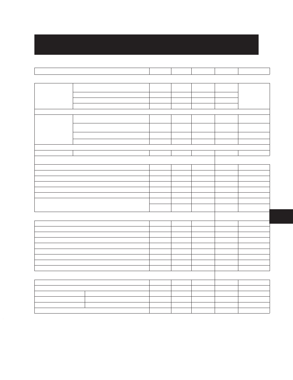
ENGINEERING DATA
Pump Size
°
6x10-22
°
8x12-21
°
8x12-22M
°
8x12-22L
8x12-27
CASING DATA
(All Dimensions in Inches)
125# FF Std.
Max. Suction Pressure (PSIG)
75
75
75
75
Not
Available
ASA Flanges
Max. Working Pressure (PSIG)
300
300
300
300
Max. Hydrostatic Test Pressure (PSIG)
450
450
450
450
Casing Material
Cast Iron
Cast Iron
Cast Iron
Cast Iron
¬
250# FF
Max. Suction Pressure (PSIG)
200
200
200
200
200
®
ASA Flanges
Max. Working Pressure (PSIG)
400
400
400
400
400
Max. Hydrostatic Test Pressure (PSIG)
¯
600
600
600
600
600
Casing Material
Ductile Iron
Ductile Iron
Ductile Iron
Ductile Iron
Ductile Iron
Casing Wall Thickness
.625
.625
.625
.625
.625
STUFFING BOX DATA
Bore
5.125
5.125
5.125
5.125
5.125
Depth
4.812
4.812
4.812
4.812
4.812
Seal Cage Width
.75
.75
.75
.75
.75
Packing No. Rings/Size Sq.
6/.625
6/.625
6/.625
6/.625
6/.625
Shaft Sleeve O.D.
3.875
3.875
3.875
3.875
3.875
Mechanical Seal Size (Type 8-1)
3.875
3.875
3.875
3.875
3.875
Å
{
Mechanical Seal
{
Major Dia.
4.125
4.125
4.125
4.125
4.125
Size (Type 8-1B)
Minor Dia.
3.875
3.875
3.875
3.875
3.875
IMPELLER DESIGN DATA
Number of Vanes
6
6
5
6
6
Inlet Area (Sq. Inches)
59
35.7
61
80
82.4
Inlet Velocity per 100 GPM (Ft/Sec)
.54
.90
.53
.40
.37
Maximum Diameter
23.0
21.8
20.5
23.0
27.0
Minimum Diameter
12.0
12.5
12.5
12.0
20.0
Maximum Sphere
1.30
1.00
1.32
1.60
1.50
WR^2 for Maximum Diameter (Lbs-Ft^2)
56
49
50
59
185
Wear Ring Clearance — Dia. BRZ Impellers
.016-.019
.016-.019
.016-.019
.016-.019
.016-.019
Wear Ring Clearance — Dia. Cl and SS Impellers
.025-.028
.025-.028
.025-.028
.025-.028
.025-.028
SHAFT AND BEARING DATA
At Coupling
3.125
3.125
3.125
3.125
3.125
Thru Impeller and Sleeves
3.311
3.311
3.311
3.311
3.311
Shaft Span
Bearing to Bearing Centerline
35.800
35.800
35.800
35.800
40.500
Ball Bearing
Inboard
6316
6316
6316
6316
6316
Outboard
21316
21316
21316
21316
21316
Frame Group
S
S
S
S
M
¬
With 250# FF flanges refer to pump as H6x10-22.
Flange dimensions are in accordance with ANSI A21.10,
AWWA C110 and ANSI B16.1 Class125.
®
Flange dimensions are in accordance with ANSI B16.1 Class
250 except flanges are flat faced.
¯
The hydrostatic test will be in accordance with the latest
edition of the Hydraulic Institute Standards, test will be
maintained for a minimum of 10 minutes.
°
6x10-22, 8x12-21, and 8x12-22M/L are standard with
125# FF suction and 250# FF discharge flanges.
±
Balanced mechanical seals have a major and a minor
diameter as listed.
7