D. indicating switch option installation, B. connect black (bk) lead to ground, C. connect brown (bn) lead to supply voltage – APTech AZ4657 User Manual
Page 2
Operation Manual
Manual Diaphragm Valves
Manual 15000004 Revision 7
Page 2 of 4
b.
For metal face seal connectors, assemble connections per standard practice described by
fitting supplier (typically 1/8 turn past finger tight).
c.
For compression-type connectors, insert the tube into the fitting until it stops. Tighten the
fitting by applying 1-1/4 turns of nut rotation.
i) For reinstallation, mark the nut and the valve body before disassembly. This will
allow the nut to be returned to the original assembly position. Insert the tube and
attached ferrules into the fitting until fully seated. Rotate the nut until it is returned to
the original assembly position, and tighten slightly beyond marked position.
d.
Most valves can be attached to panels or mounting plates using the 10-32 or M5 female
thread mounting holes located in the bottom of the body (valves with M5 mounting holes
will be marked with a “5” on the bottom of the body). Special configurations or multi-
valve blocks may not have mounting holes or may have different size holes. Refer to the
specific data sheet or Technical Bulletin for detailed mounting information.
4. After installation, perform a leak test of all connections and welds per standard industry
practice (reference SEMI standard F1).
D. Indicating Switch Option Installation
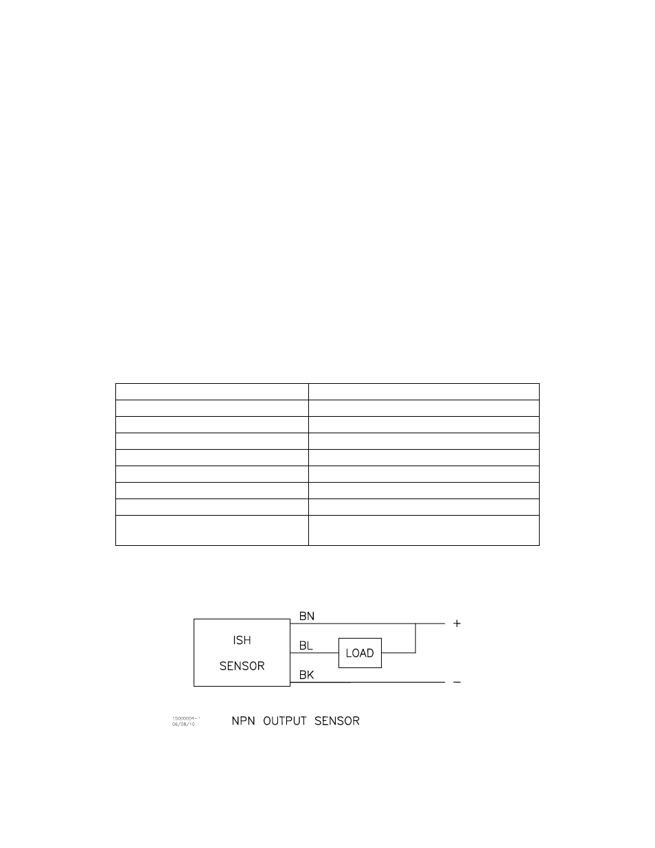
1. ISH option for AK/AP/AZ3650 or AK/AP/AZ4650 (refer to Figure 1):
a.
Review the following specifications to verify the switch is appropriate for the installation.
Switch model
Honeywell 2SS52M
Switch type
NPN (current sinking)
Operating temperature
-40 to 150 C
Supply voltage
3.8 to 30.0 VDC
Output voltage
0.4 VDC max.
Supply current
11 mA max.
Output current
20 mA max.
Life expectancy
up to 5,000,000 cycles at 1.2 VA
Connectors
Stranded 24 AWG wire (blue, black, and
brown leads)
b.
Connect black (BK) lead to ground.
c.
Connect brown (BN) lead to supply voltage.
d.
Connect blue lead (BL) to load that is connected to supply voltage.
Figure 1. ISH Sensor Wiring Diagram
- AP4657 AK4657 AZ4652 AP4652 AK4652 AZ4650 AP4650 AK4650 AZ4625 AP4625 AK4625 AZ4600 AP4600 AK4600 AP3900 AP3800 AZ3657 AP3657 AK3657 AZ3652 AP3652 AK3652 AK3625 AZ3650 AP3650 AK3650 AZ3627 AP3627 AK3627 AZ3625 AP3625 AZ3624 AP3624 AK3624 AZ3604 AK3604 AZ3600 AP3600 AK3600 AP3260 AP3157 AP3150 AP3125 AP3102 AP3100