Step four: start up, Warranty information, Step three: installation of fabric diffuser – Air Distribution Concepts Cable User Manual
Page 4
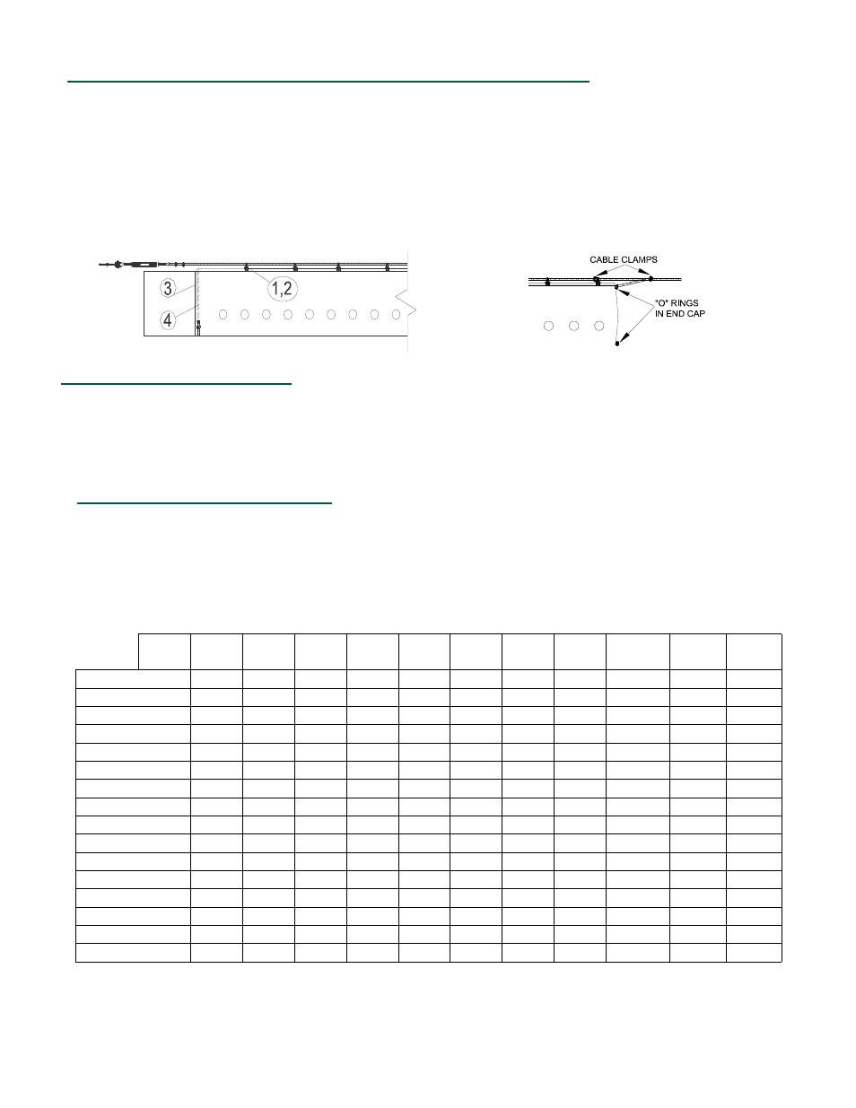
STEP FOUR: START UP
Turn on air handler and inflate diffuser. With the diffuser inflated, anchor the end cap or last snap hook of the
diffuser to the support cable as shown. This will keep the diffuser fully extended when diffuser is deflated and keep
the diffuser from sliding.
If the diffuser system flutters after installation, check to see if air handler is operating at its designed air volume
and static pressure. Fluttering can cause damage to fabric shortening life of system.
WARRANTY INFORMATION
Diffuser systems are subject to a five year limited warranty. The warranty covers workmanship and materials on all
components of the system. Only replacement costs and credits are covered. Cash payments are not available.
The warranty covers freight costs, but does not cover installation costs. The warranty excludes damage caused by
improper installation, failure to specify all system requirements and air handling equipment not performing as
specified. The effective start date of the warranty is the product ship date.
STEP THREE:
INSTALLATION OF FABRIC DIFFUSER
When handling a diffuser prior and during installation, please keep anything that comes in contact with the diffuser
clean. If a diffuser is to be laid out on the floor, make sure floor is clean or something is laid down to protect diffuser
from dirt or debris on the ground that could catch on air jets and damage diffuser during installation.
1.) Attach the diffuser’s snap hooks to the cable.
2.) Pull diffuser down cable until fully extended.
3.) Pull open end of diffuser and slip over metal collar or metal duct (about 6-12”).
4.) install worm gear band around diffuser to secure it to metal duct.
Note: Worm gear bands are perforated and self taping screws can be used to help secure band and
keep from slipping. ( screws not included).
CABLE TENSION CHART ( AMOUNT OF SAG (in inches) BASED ON CABLE TENSION OF 500 LBS.)
LENGTH IN FEET
25
50
75
100
125
150
175
200
225
250
275
300
DIA."
12
0.35
1.41
3.17
5.63
8.80
12.67
17.25
22.53
28.51
35.20
42.59
50.68
18
0.49
1.97
4.44
7.89
12.33
17.76
24.17
31.57
39.96
49.33
59.69
71.03
20
0.54
2.16
4.86
8.65
13.51
19.45
26.48
34.58
43.77
54.04
65.39
77.81
24
0.63
2.54
5.71
10.15
15.86
22.84
31.09
40.61
51.40
63.46
76.78
91.38
30
0.78
3.10
6.98
12.41
19.40
27.93
38.02
49.66
62.85
77.59
93.88
111.73
36
0.92
3.67
8.25
14.67
22.93
33.02
44.94
58.70
74.29
91.72
110.98
132.07
38
0.96
3.86
8.68
15.43
24.11
34.71
47.25
61.71
78.11
96.43
116.68
138.86
42
1.06
4.23
9.53
16.94
26.46
38.11
51.87
67.74
85.74
105.85
128.08
152.42
48
1.20
4.80
10.80
19.20
29.99
43.19
58.79
76.79
97.18
119.98
145.17
172.77
52
1.29
5.18
11.65
20.70
32.35
46.58
63.40
82.81 104.81
129.40
156.57
186.33
56
1.39
5.55
12.49
22.21
34.70
49.97
68.02
88.84 112.44
138.82
167.97
199.90
62
1.53
6.12
13.77
24.47
38.24
55.06
74.94
97.89 123.89
152.95
185.07
220.24
68
1.67
6.68
15.04
26.73
41.77
60.15
81.87 106.93 135.33
167.08
202.16
240.59
74
1.81
7.25
16.31
28.99
45.30
65.23
88.79 115.97 146.78
181.21
219.26
260.94
76
1.86
7.44
16.73
29.75
46.48
66.93
91.10 118.99 150.59
185.92
224.96
267.72
84
2.05
8.19
18.43
32.76
51.19
73.71 100.33 131.04 165.85
204.76
247.76
294.85
EXAMPLE: 30” DIA. X 200 ft. diffuser would have a sag of about 50”. With one vertical support 100 ft. in the sag
is reduced to 12.41” and two supports at, (66 ft. & 132 ft.) would reduce the sag between supports to about 5”.