Barksdale L2H User Manual
Page 7
Contacts: color code and function
Contacts
C
= Common
= purple
NC
= Normally
Closed
Contact
= blue
NO
= Normally
Open Contact
= red
Contacts: color code and function
Lower contacts
Upper contacts
C
= Common
= purple
C
= brown
NC
= Normally
Closed
Contact
= blue
NC
= orange
NO
= Normally
Open Contact
= red
NO
= yellow
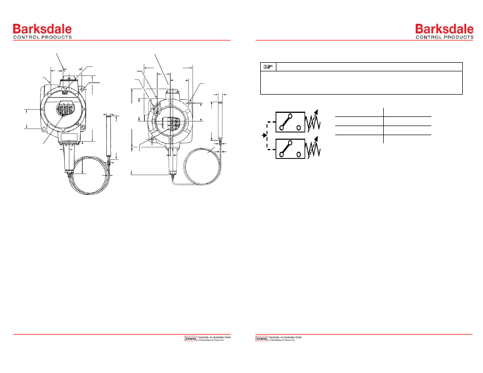
Fig. 8: Temperature switch type T1X-…/T1X-EX…
Fig. 9:Temperature switch type T2X-…/T2X-EX...
IMPORTANT
Adjustment of several set points is performed for each set point as specified above.
Due to the sluggishness of the capillary system switching delays may occur in case of rapid
temperature changes (>2 °C/Minute).
Wiring Code for all Types (Contact status at atm. pressure)
Power circuit
1
Power circuit
2
C = purple
C = brown
NC = blue
NC = orange
NO = red
NO = black
Circuit
1 = lower contact (low)
Circuit
2 = upper contact (high)
Fig. 5
Wiring Code
Use in Hazardous Locations
The weather-proof standard temperature switches must not be used for hazardous locations.
Special temperature switch types; T1X-EX, T2X-EX and L1X-EX for Ex d IIC T6 explosion-proof
applications with Certificate No. ISSeP 08 ATEX 024X.
These special models are suitable for gas and dust applications and approved for Ex II G D in
accordance with the ATEX 94/9/EC regulations.
These special switches with explosion-proof enclosure must be wired with Ex Certified conduit
connection, or cable gland. The switches may only be used in accordance with the instructions and
provisions of the declaration of conformity.
½“ NPT conduit
connection
46 (1.81)
10
2
(
4
.016)
16
0
(
6.
3)
75
(2.
95)
28.6 (1.13)
Ground screw
(internal)
Mounting holes
ø7.1 x 2
46
(
1.
81)
ш4.75
(0.11)
ш2.4
(0.09)
Terminal strip for
three connections
14.3
(0.56)
25.4 mm (1.0 inch) min.
required to remove the cover.
25.4 mm (1.0 inch) min.
required to remove the cover.
Terminal strip for
three connections
6.4
(0.25)
73 (
2.
8
7
)
161 (
6.
3
4
)
63.
5 (
2.
5)
11
3
(
4.
45)
ш4.75 (0.11)
ш2.4 (0.09)
ш9.6
(0.38)
*
**
* ¾“ NPT conduit
connection
** Ground screw
(internal)
136 (5.35)
Mounting holes
ø7.1 x 2
51
(2.008)
36.5 (1.44)
5
1
(2
.0
08)
Adjustment knob under cover
Adjustment knob under cover
NO
NC
C
NO
NC
C
1
2
7
10