Automation Components ACI/ACI RH Room Series User Manual
Page 2
2305 Pleasant View Rd. Middleton Industrial Park Middleton, WI 53562
PH: (608) 831-2585 FAX (608) 831-7407
I0000144.DOC REV 2
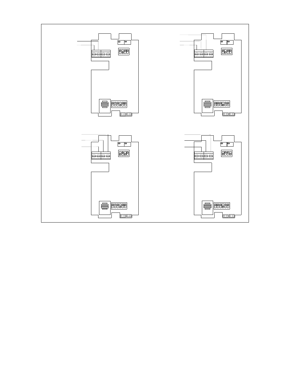
15 - 36 VDC or 21.6 - 26.4 VAC Input / 0 - 5 VDC Output
15 - 36 VDC Input / 4 - 20mA Output
15 - 36 VDC Supply Voltage
Figure # 4
15 - 36 VDC Supply Voltage or
21.6 - 26.4 VAC Supply Voltage
Supply Ground / Signal Common
0 - 5 VDC Output
Io
4 - 20mA Output
Io
4
Vin Gnd
Zero
Vo
6
5
S2
SW3
S1
SW2
3
2
4
3
1
ON
2
1
ON
Span
4
Vin Gnd
Zero
Vo
6
5
S2
SW3
S1
SW2
4
3
3
2
2
ON
1
1
ON
Span
18 - 36 VDC Supply Voltage or
21.6 - 26.4 VAC Supply Voltage
Supply Ground / Signal Common
0 - 10 VDC Output
4 - 20mA Output
21.6 - 26.4 VAC Supply Voltage
Supply Ground / Signal Common
ON
SW3
ON
SW3
21.6 - 26.4 VAC Input / 4 - 20mA Output
18 - 36 VDC or 21.6 - 26.4 VAC Input / 0 - 10 VDC Output
Gnd
Io Vin
Zero
Vo
6
5
4
3
4
SW2
ON
S1
2
1
3
2
Gnd
Io Vin
Zero
Vo
6
5
S1
4
4
3
SW2
ON
3
2
2
1
Span
S2
1
Span
S2
1
RH Test and Calibration Dip Switch Settings (See Figure #3)
Note: Do not adjust these switches unless you are using them to troubleshoot or recalibrate the sensor. Dipswitch #3
should always be left in the ON position. Failure to do so will not allow the RH transmitter to read the sensor (The
output will always remain the same).
0% RH Output - Transmitter always outputs a signal of 4 mA or 0 VDC. Sensor doesn’t affect the transmitter
output. (For Trouble Shooting Purposes Only)
50% RH Output - Transmitter always outputs a signal of 12 mA, 2.5 VDC, or 5 VDC. Sensor doesn’t affect the
transmitter output. (For Trouble Shooting Purposes Only)
100% RH Output - Transmitter always outputs a signal of 20 mA, 5 VDC, or 10 VDC. Sensor doesn’t affect the
transmitter output. (For Trouble Shooting Purposes Only)
Normal Operating Condition - The DIP switch must be set in this position for the RH signal to change, due to the
actual measurement of the Relative Humidity by the humidity sensor.
Increment RH Output - This DIP switch will allow you to calibrate the sensor through the software. The switch
must be toggled from the Off to the On position and then returned to the Off position for an
increase of 0.5% RH. This means that if your humidity has drifted 1% over a certain time
period, you will be able to toggle the Increment RH Output switch (2) times in order to
slide the whole curve upward 1%. Note: This is only a single point calibration, and is not
recommended for critical applications. Please contact the factory before doing any
field calibration.