Automation Components ACI/TT-RSO-LCD User Manual
Page 2
2305 Pleasant View Rd. Middleton Industrial Park Middleton, WI 53562
PH: (608) 831-2585 FAX: (608) 831-7407
II-26
All ACI/TT and TTM temperature transmitters are non-polarity sensitive. That means that, the positive and negative
outputs of the power supply can be connected to either side of the power terminal block.
N = I mA
22
where: N = number of transmitters
I = current available from power supply
22mA = maximum current draw of transmitter
e.g.,
If I = 1.5A then:
N = 1.5/22mA
N = 68
Therefore a 1.5A power supply will safely power up to 68 transmitters.
n
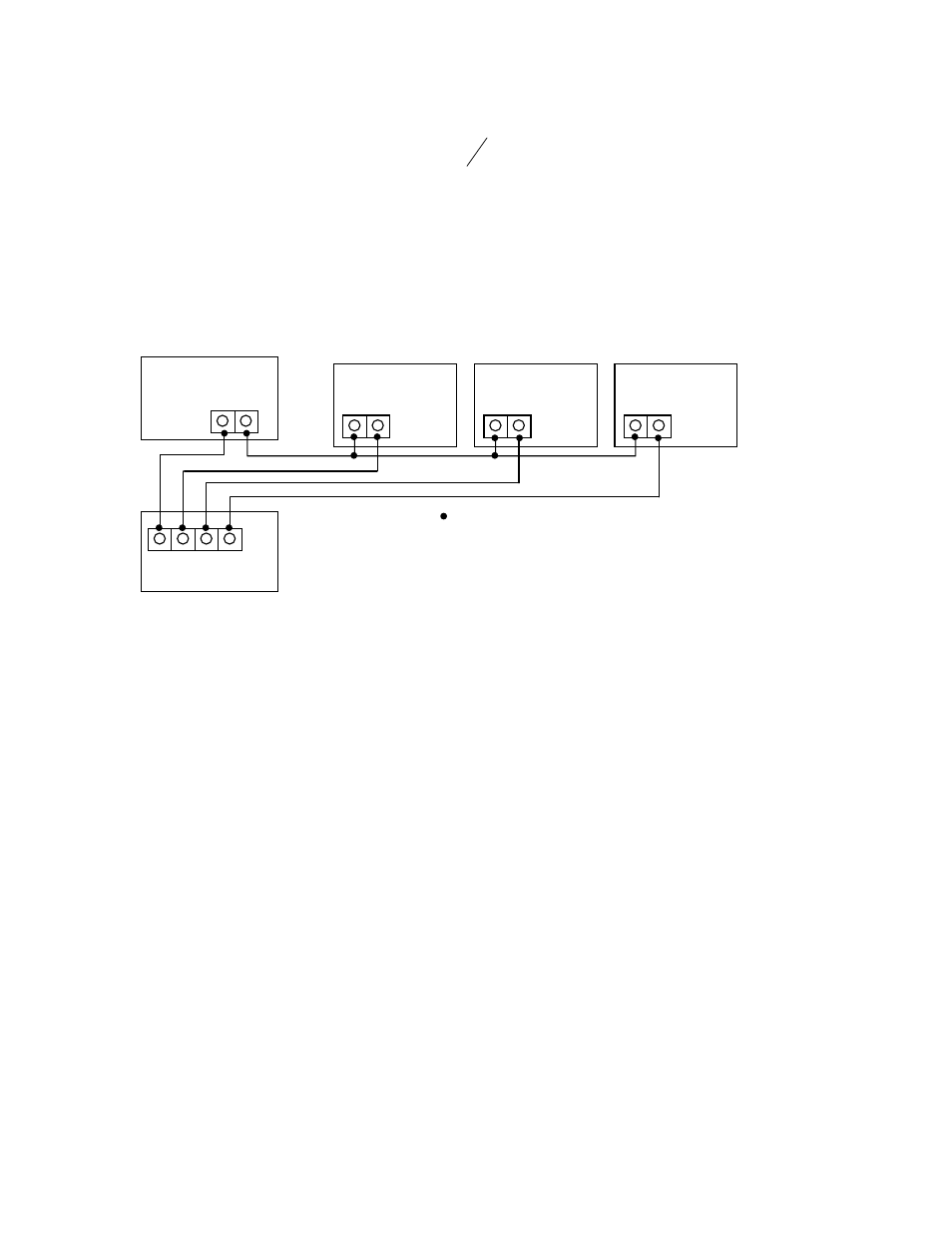
SYSTEM WIRING DIAGRAM
n
ROOM TEMPERATURE TRANSMITTERS
This unit is suitable for either drywall or junction box mounting. First, remove the cover of the enclosure and mount the
base of the Room unit to the wall, using the (2) 6/32” x 1” screws that are provided. Once the base is mounted to the
wall, make all of the proper connections and then place the cover back onto the unit. Now fasten the cover, using the
(2) 1/16” Allen screws located at the bottom of the enclosure.
Power Supply
+ -
+ -
+ -
Temp.Transmitter #1
Temp.Transmitter #N
Temp.Transmitter #2
-
VDC
+
Controller
Gnd In1 In2 In3
= Connections
In1 = Controller Input #1
In2 = Controller Input #2
In3 = Controller Input #3