页 17, Installing the light kit assembly – Minka Group F759-PBL User Manual
Page 17
8
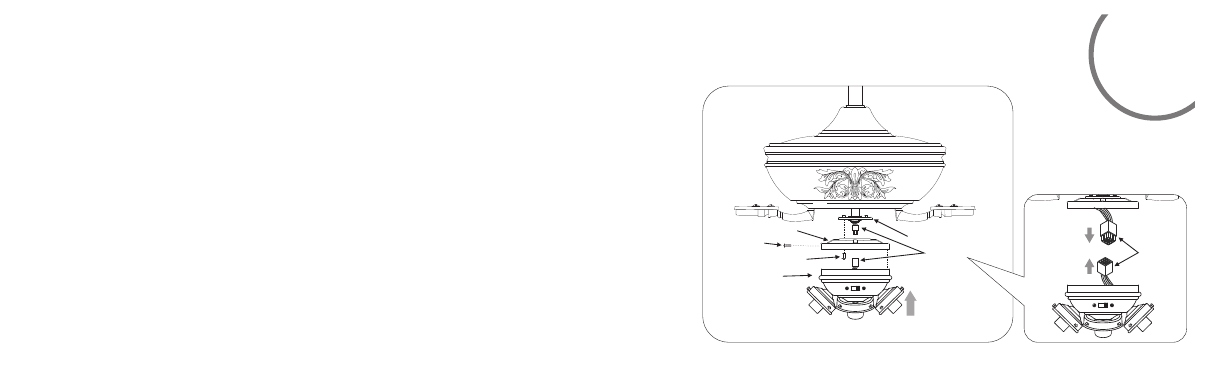
INSTALLING THE LIGHT KIT ASSEMBLY
Fig 17
Mounting ring
Screw
Light kit plate
Light kit
assembly
Screws
Connection plug
Connection plug
Step1. Remove the light kit plate from the light kit assembly by removing three
screws from the rim of the light kit plate and reserve the screws.
Step2.Remove 1of 3screws from the mounting ring and loosen the other 2
screws.(Do not remove.) (Fig.17)
Step3.Place the key holes from the light kit plate over the 2 screws previously
loosened from the mounting ring , turn light kit plate until it locks in place at
the narrow section of the key holes. Secure by tightening the 2 screws
previously loosened and the one previously removed.(Fig.17)
Step4.While holding the light kit assembly under your fan, firmly snap the wire
connection plugs together.(Fig.17)
Step5.Align the holes in the light kit assembly with the holes in the light kit plate.
Tighten the three screws removed in step1.(Fig. 17)
- F689-PW (24 pages)
- F582-ORB (26 pages)
- F539-BCW (24 pages)
- F518-WH (22 pages)
- F705-STW (9 pages)
- F620-BCW (27 pages)
- F402-ORB (25 pages)
- F513-BN (24 pages)
- F614-DBB (23 pages)
- F823-DK (24 pages)
- F695-KA (23 pages)
- F701-DRB (15 pages)
- F547-BS/DW (15 pages)
- F572-WH (9 pages)
- F566-WH (12 pages)
- F753-BNW (24 pages)
- F510-BS (24 pages)
- F522-WH (26 pages)
- F581-BG (14 pages)
- F659-PBL (24 pages)
- F889-ORB (26 pages)
- F733-BK/RW (24 pages)
- F696-KA (24 pages)
- F565-WH (13 pages)
- F734-SI (25 pages)
- F514-BN (30 pages)
- F594-WH (23 pages)
- F603-BN (15 pages)
- F711-PW (23 pages)
- F888-ORB (26 pages)
- F544-GBZ (22 pages)
- F707-FLP (24 pages)
- F521-ORB (26 pages)
- F548-WH (24 pages)
- F803-LN (27 pages)
- F637-ORB (22 pages)
- F647-SWH (23 pages)
- F563-SP-BS/DW (23 pages)
- F588-SP-BN (25 pages)
- F524-ABD (22 pages)
- F571-DRF (22 pages)
- F302-BN (23 pages)
- F602-BN/CH (26 pages)
- F833-SL (22 pages)
- F853-BN/MM (24 pages)