Attaching the switch cup – Minka Group F532-BWH User Manual
Page 16
8
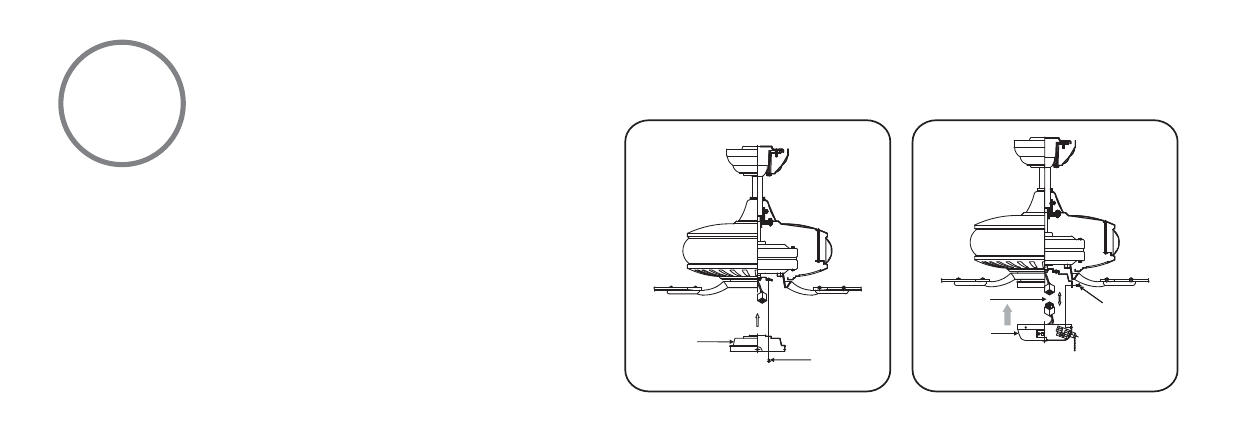
Step 1. Remove the screws from the motor housing, place the
switch cup plate over the motor housing and align the holes.
Secure in place with screws previously removed. (Fig. 17)
Step 2. Remove the screws from the switch cup plate. Place
the switch cup close to the switch cup plate, align the plastic
connectors from switch cup and the switch cup plate and
firmly snap the two connectors. Assemble the switch cup to
the switch cup plate by tightening the screws previously
removed. (Fig. 18)
Fig 17
Fig 18
SWITCH
CUP PLATE
SCREWS
SWITCH CUP
SCREWS
MOLEX
ATTACHING THE SWITCH CUP
See also other documents in the category Minka Group Fans:
- F689-PW (24 pages)
- F582-ORB (26 pages)
- F539-BCW (24 pages)
- F518-WH (22 pages)
- F705-STW (9 pages)
- F620-BCW (27 pages)
- F402-ORB (25 pages)
- F513-BN (24 pages)
- F614-DBB (23 pages)
- F823-DK (24 pages)
- F695-KA (23 pages)
- F701-DRB (15 pages)
- F547-BS/DW (15 pages)
- F572-WH (9 pages)
- F566-WH (12 pages)
- F753-BNW (24 pages)
- F510-BS (24 pages)
- F522-WH (26 pages)
- F581-BG (14 pages)
- F659-PBL (24 pages)
- F889-ORB (26 pages)
- F733-BK/RW (24 pages)
- F696-KA (24 pages)
- F565-WH (13 pages)
- F734-SI (25 pages)
- F514-BN (30 pages)
- F594-WH (23 pages)
- F603-BN (15 pages)
- F711-PW (23 pages)
- F888-ORB (26 pages)
- F544-GBZ (22 pages)
- F707-FLP (24 pages)
- F521-ORB (26 pages)
- F548-WH (24 pages)
- F803-LN (27 pages)
- F637-ORB (22 pages)
- F647-SWH (23 pages)
- F563-SP-BS/DW (23 pages)
- F588-SP-BN (25 pages)
- F524-ABD (22 pages)
- F571-DRF (22 pages)
- F302-BN (23 pages)
- F602-BN/CH (26 pages)
- F833-SL (22 pages)
- F853-BN/MM (24 pages)