Lectrical, Onnections – Minka Group F581-ORB User Manual
Page 7
5. E
LECTRICAL
C
ONNECTIONS
WARNING: To avoid possible
electrical shock be sure electricity is
turned off at the main fuse or breaker
box before wiring.
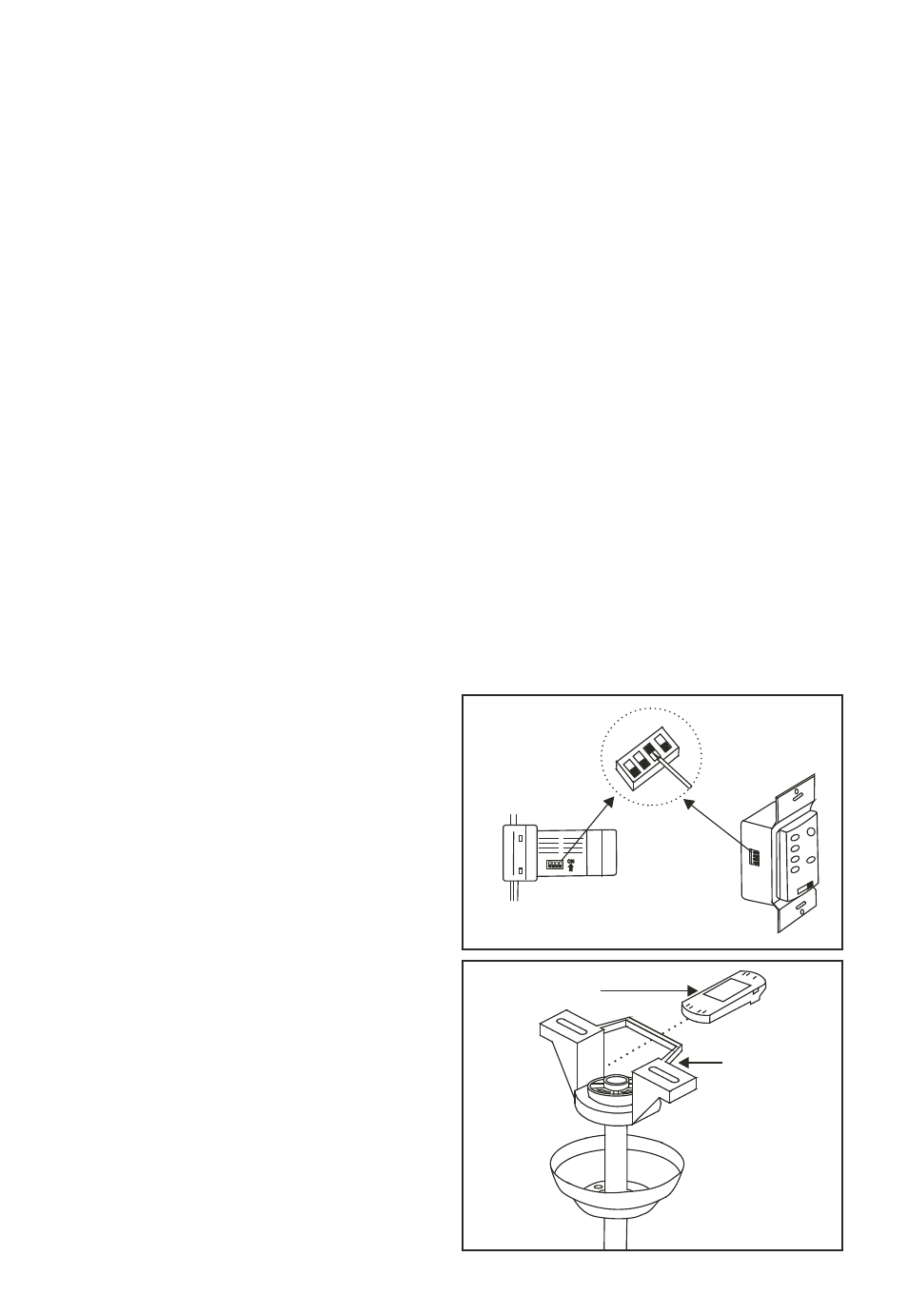
NOTE: The Hand Held Remote or
Wall Control units included with your
ceiling fan are equipped with 16 code
combinations to prevent possible
interference from or to other remote
units. The frequency switches on your
Receiver and Transmitter units have
been preset at the factory, please re-
check to make sure the switches on
both units are set to the same positions.
The frequency settings should be
changed only in case of interference or
if a second or more remote controlled
ceiling fans are installed in the same
structure. Any code combination will
operate the ceiling fan and light as long
as the Receiver and Transmitter units
are set to the same codes (Fig. 11)
Step 1. Insert Receiver into Hanger
Bracket with the flat side of the
Receiver facing the ceiling. (Fig. 12)
Step 2. Motor to Receiver Electrical
Connections: Connect the WHITE
wire from the fan to the WHITE wire
marked "TO MOTOR N" from the
Receiver. Connect the BLACK wire
from the fan to the BLACK wire
marked "TO MOTOR L" from the
Receiver. Connect the BLUE wire from
the fan to the BLUE wire marked "For
Light" from the Receiver. NOTE: If
your ceiling fan features an UP Light:
Connect the ORANGE wire from the
fan to the ORANGE wire marked "For
Up Light" from the Receiver.
Otherwise disregard this step and
proceed to secure all wire connections
with the plastic wire nuts provided.
(Fig. 13 & 14)
Step 3. Receiver to House Supply Wires
Electrical Connections: Connect the
WHITE wire (Neutral) from the outlet
box to the WHITE wire marked "AC in
N" from the receiver. Connect the
BLACK wire (Hot) from the outlet box
to the BLACK wire marked "AC in L"
from the receiver. Secure all wire
connections with the plastic wire nuts
provided. (Fig. 13 & 14))
Step 4. If your outlet box has a
GROUND wire (Green or Bare Copper)
connect this wire to the Hanger Ball and
Hanger Bracket Ground wires. If your
outlet box does not have a Ground Wire,
then connect the Hanger Ball and
Hanger Bracket Ground Wires together.
Secure wire connection with the plastic
wire nut provided. (Fig. 13 & 14)
After all splices are made, check to make
sure there are no loose strands. As an
additional precaution we suggest to
secure the plastic wire connectors to the
wires with electrical tape.
Fig. 11
Fig. 12
Receiver
Hanger bracket