Anging the – Minka Group F581-ORB User Manual
Page 6
H
ANGING THE
F
AN
4.
Outlet box
Hanger bracket
Downrod
Supply
wires
Figure 5
Figure 7
Figure 8
Figure 6
Figure 10
Registration
slot
Cross pin
Hanger
ball
Downrod
Hitch
pin
Lock
pin
Set
screws
Screw
Fig. 9
Downrod
Coupling
*Omit coupling
cover when
downrod
cover
using
the minimum-length
Canopy
Set screws
Hitch pin
Lock pin
Downrod
rubber cover
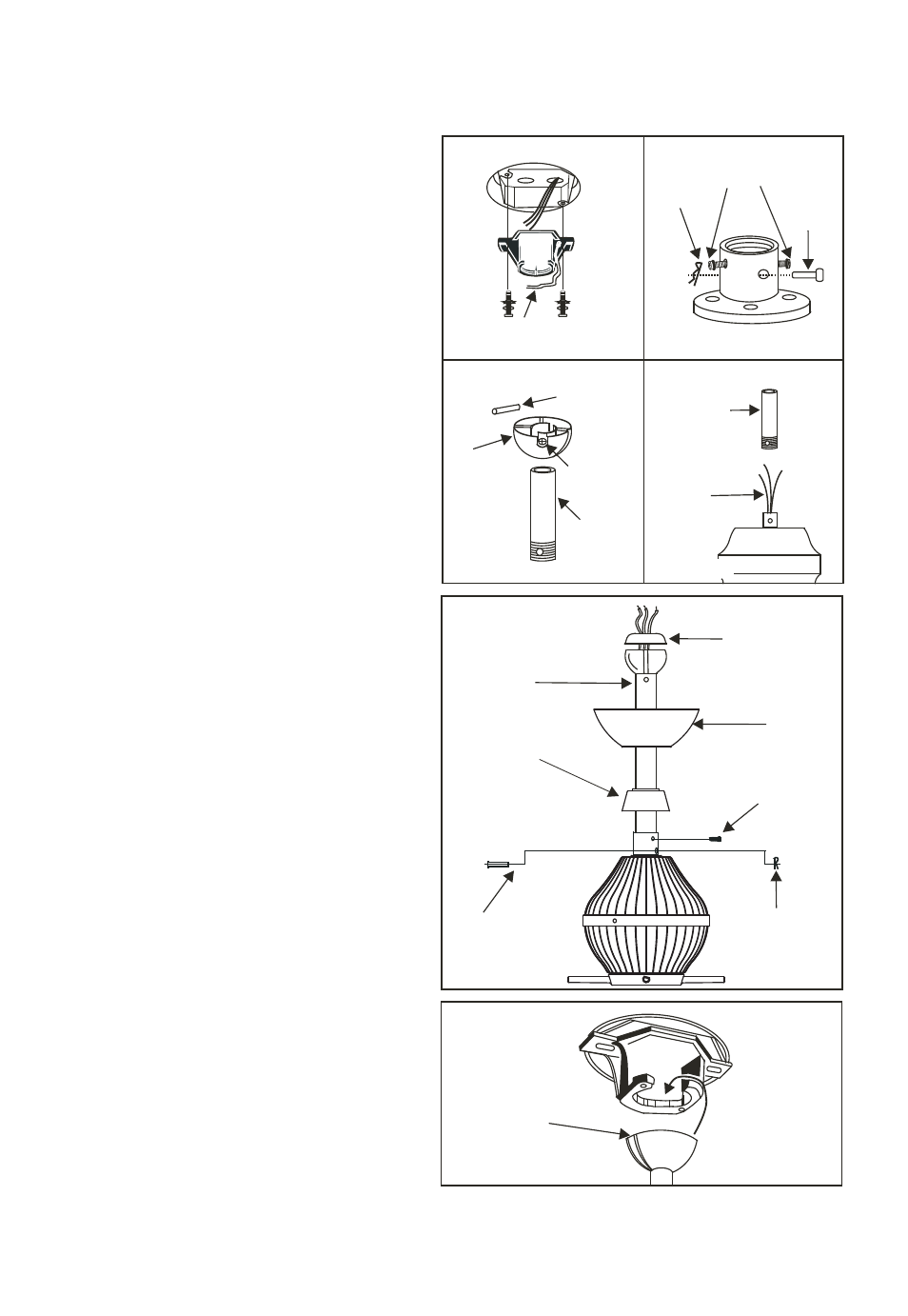
REMEMBER to turn off the power.
Follow the steps below to hang your
fan properly:
Step 1. Secure the hanger bracket to
the ceiling outlet box using screws
included with your outlet box, lock
washers included with the fan. (Fig.5)
Step 2. Loosen the two set screws and
remove the hitch pin and lock pin in
the top coupling of the motor
assembly. (Fig. 6)
Step 3. Remove hanger ball from
downrod assembly by loosening set
screw, removing the cross pin, and
sliding ball off rod. (Fig.7)
Step 4. Carefully feed fan wires up
through the downrod. (Fig. 8) Thread
Downrod into the Coupling until the
holes are lined up and secure with the
Lock Pin and Hitch Pin previously
removed, tighten Set Screws. (Fig. 9)
Step 5. Slip coupling cover and
canopy onto downrod. (Fig. 9)
Carefully reinstall hanger ball onto
rod being sure that cross pin is in
correct position, set screws are tighten
and wires are not twisted.
Step 6. Place downrod rubber cover
onto the hanger ball, then re-install
the hanger ball onto the downrod
making sure the crosspin is in correct
postion, set screw is tight and wires
are not twisted. (Fig. 9)
Step 7. Lift the Motor Assembly and
place the Hanger Ball into the Hanger
Bracket. Rotate the Motor Assembly as
needed until the check groove from
the Hanger Ball rests firmly over the
registration tab from the Hanger
Bracket. Motor Assembly should not
rotate if this is done correctly. (Fig. 10)