Gear mesh, Gear mesh :: ride height, Adjusting ride height – Team Associated APEX Touring Brushless Powered User Manual
Page 9
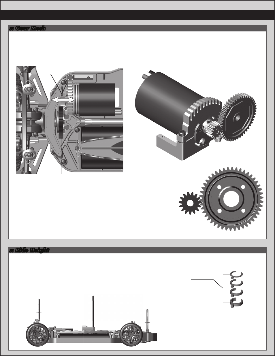
Gear Mesh:
To correctly set your gear mesh, follow the steps below:
1. Remove the Chassis Brace. Loosen the set screw on the motor’s pinion gear. Slide the pinion on the motor shaft
until the gear face of the pinion is entirely aligned with the gear face of the spur gear (see diagram). Tighten the set
screw while ensuring it is aligned with the flat face on the motor shaft.
2. Loosen the motor clamp screw until the motor is able to move freely.
Rotate the motor as far as it can go towards the spur gear, ensuring that
the teeth of the pinion and the spur gear are interlocking. Slide the motor
back (approximately 0.5 mm), and tighten the motor clamp screw.
Proper gear mesh has been achieved when the teeth are meshing closely,
but the gears still have a small amount of clearance between them. If you hold
one gear, you should be able to rock the other gear back and forth a small
amount. If there is no clearance, your gear mesh is too tight and you should
readjust the motor again.
9
:: Gear Mesh
:: Ride Height
Pinion
Spur Gear
7149
Shock
pre-load
clips
Front shock: 4mm
Rear shock: 4mm
6mm
4mm
2mm
1mm
Adjusting Ride Height:
Ride height is adjusted by adding and /or removing shock pre-load clips to the front
and rear shocks. Stock setting is approximately 4mm front and rear. Check the
ride height with the FT Ride Height Gauge (#1450). Raise or lower the ride height
with the shock clips as necessary and recheck.
Pinion
Spur Gear