Lcdd32 device driver, Page 3 of 3, Warranty – Pathway Programmable Device Driver - #LCDD32 User Manual
Page 3: Test mode, Connections for momentary output, Support
Technical support is available from Pathway Connectivity
at +1 (403) 243-8110, Monday to Friday, from 9 a.m. to 5
p.m. Mountain time. Please have the unit model number
and serial number ready when you call.
The Gray LCCDD32P Device Driver is covered by a one
year warranty against defective parts and labor. If you
need to return anything for any reason, contact the
factory in advance for return instructions.
WARRANTY
LCDD32 DEVICE DRIVER
Page 3 of 3
TEST MODE
DS-7 must be OFF and DS-8 ON. The “TEST”
LED will be on.
Output Test: DS-4 must be off. The DMX address
switches select the output number to test. The selected
device can then be turned on by pressing the program
pushbutton. If the number is out of the correct range (000
to 032, or 000 to 016 in momentary mode) the "TEST"
LED will flash to indicate an error when the button is
pressed.
DMX Test Function: The DMX receive LED (RxD) will
be on and steady if a valid DMX signal is received. If no
DMX signal is present the LED will be off, and if the DMX
signal is not valid the LED will flash continuously.
Patch Testing Mode: DS-4 must be on. The address
switches select the DMX channel #. When the program
pushbutton is pressed, devices assigned to that DMX
channel # will turn ON. When the pushbutton is released
those devices will turn OFF. The "TEST" LED will flash
once if there is an error in the address range selection.
APPLICATION NOTES
The LCDD32 Programmable Device Driver can be used
to operate a wide variety of on/off (non-dim) DC devices.
It can control maintained action devices include solid
state relays, electrically held (maintained action) relays,
contactors and solenoids, LED and lamp displays. It can
also be used to control mechanically latching (momentary
pulsed) devices, such as GE RR series relays. All of
these devices can be placed under DMX512 or optional
master switch control.
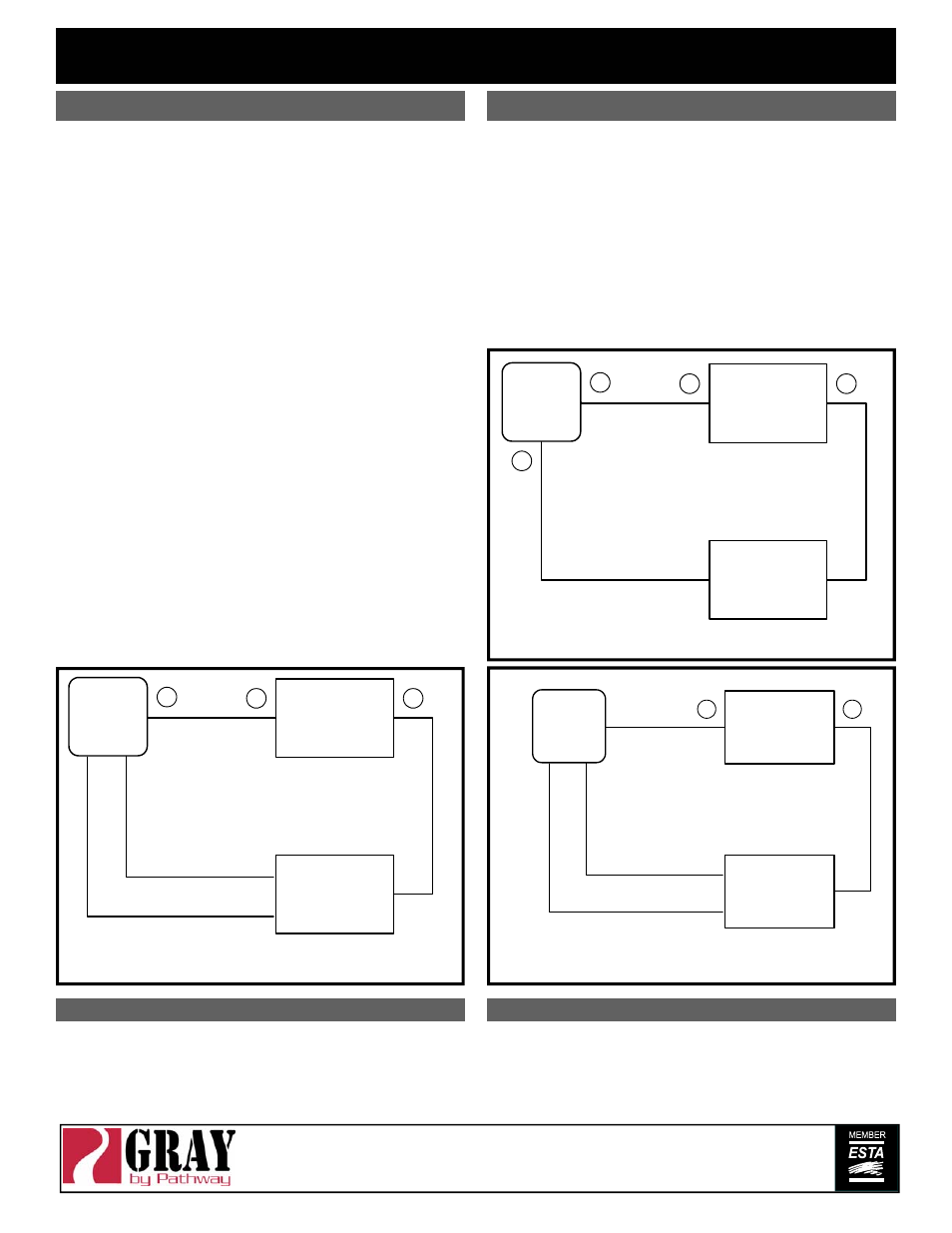
The following illustrations show typical connection details.
Relay power
supply
24 VDC
(by others)
LCDD32
+
-
Relay
(by others)
ON (odd #s)
OC
OFF (even #s)
Outputs
typical of 16 pairs
Blue
Red
Black
Connections for GE RR Series relays
Connections for Maintained Output
Device power
supply
5-48 VDC
(by others)
LCDD32
+
-
+
-
DC
DEVICE
(by others)
Output
OC
typical of 32
Connections for Momentary Output
Device power
supply
5-48 VDC
(by others)
LCDD32
+
+
-
DC
DEVICE
(by others)
ON (odd #s)
OC
OFF (even #s)
Outputs
typical of 16 pairs
SUPPORT
rev0 ver2.0
2
09/03
Printed in Canada
www.pathwayconnect.com
Pathway Connectivity Inc., 480C - 36 Avenue S.E.,
Calgary, AB, T2G 1W4 Canada
tel (403) 243-8110 fax (403) 287-1281