Lcdd32 device driver, Page 2 of 3 – Pathway Programmable Device Driver - #LCDD32 User Manual
Page 2
LCDD32 DEVICE DRIVER
Page 2 of 3
Program Patch:
DS-5 OFF, DS-6 OFF, JP1 open
The address switches set the equivalent DMX channel #
(001 to 512) and the device switches select the output
number (01 to 32). Pressing the program store
pushbutton (S6) to store the patch assignment will cause
the program (PROG) LED to flash once unless an
incorrect DMX # or device # has been selected.
NOTE:
Address 000 is used to clear the patch
assignment for the selected relay. Each device can be
assigned to only one DMX channel. A new assignment for
a device overwrites the previous assignment for that
device.
Clear Patch:
DS-5 OFF, DS-6 OFF, JP1 shorted
The entire patch will be cleared when the program
pushbutton is pressed. The "PROG" LED will flash once
to indicate a successful execution.
Program Master Sw.A:
DS-5 ON, DS-6 OFF, JP1 open
The OUTPUT# switches select the device number to
connect. The program (PGM) pushbutton is pressed to
execute. The “PROG” LED will flash once unless an
incorrect device number has been selected. The “TEST”
LED will illuminate to indicate that the selected device has
been assigned to the switch input. Repeat this procedure
to add additional devices to this switch.
Program Master Sw.B:
DS-5 OFF, DS-6 ON, JP1 open
Follow the same procedure as above for Master Switch A.
Verify: To check the connection between a master
switch and an assigned device, set the OUTPUT#
switches to the desired device and the connect status will
be indicated by the "TEST" LED (ON if connected, OFF if
not connected). To set or clear the connection, simply
toggle the program button. Each master switch can be
connected to any combination of valid outputs. Master
switches can only be tested while in the program mode.
Clear Master Sw.A:
DS-5 ON, DS-6 OFF, JP1 shorted
Press the program pushbutton to clear all output
connections to master switch A. The "PGM" LED will flash
once.
Clear Master Sw.B:
DS-5 OFF, DS-6 ON, JP1 shorted
Press the program pushbutton to clear all output
PROGRAMMING
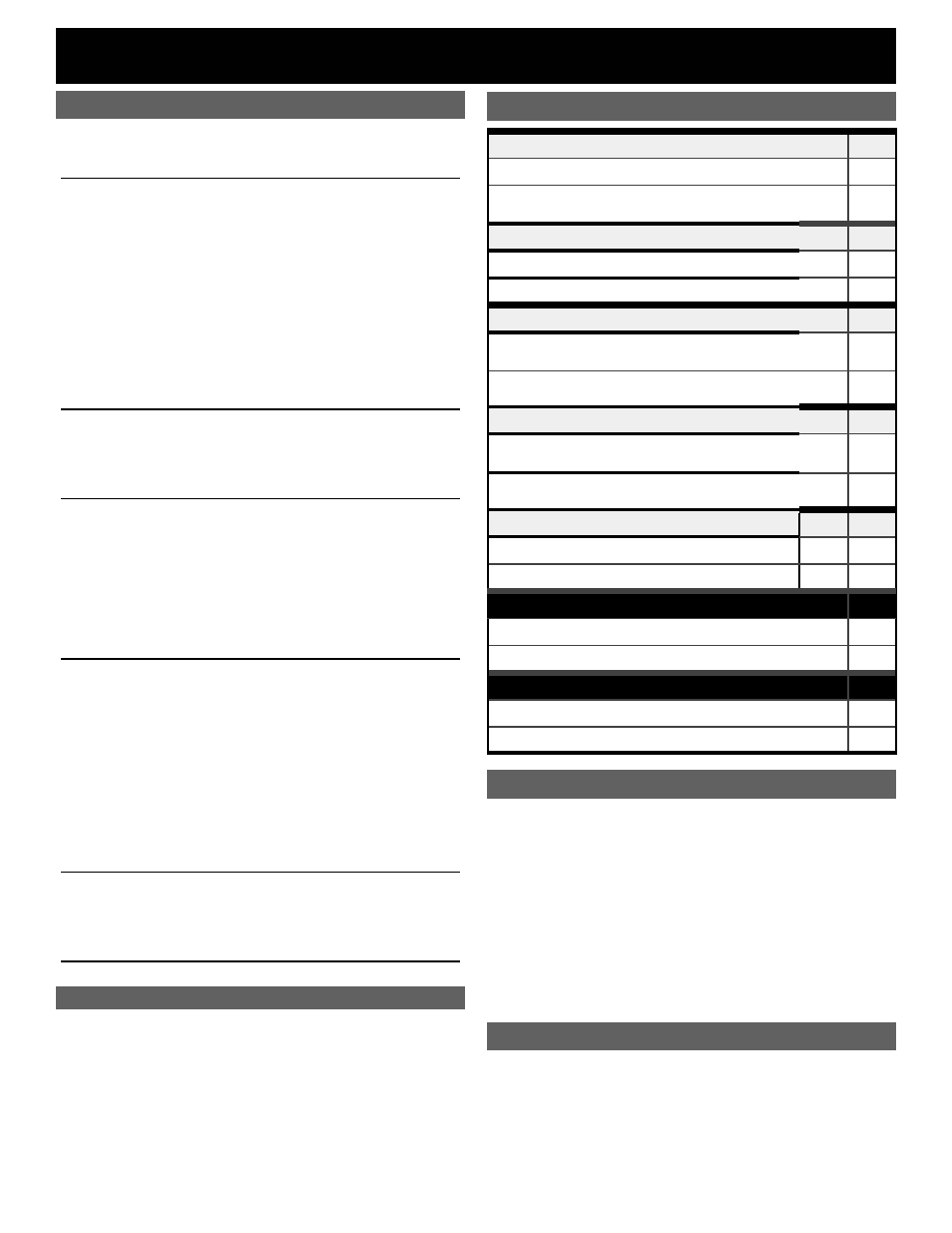
OUTPUT MODE
DS-1
All Maintained: (32 channels) Constant output
OFF
All Momentary: (16 channels) 100 ms pulse for latching
relays
ON
THRESHOLD SELECT
DS-2
25% Threshold (on at 30%, off at 20%)
ON
75% Threshold (on at 80%, off at 70%)
OFF
OUTPUT SCAN MODE
DS-3
Scan Mode Enabled
Turns outputs on or off in sequence, 10 per second
ON
Scan Mode Disabled
Turns outputs on or off simultaneously
OFF
CONTROL MODE
DS-4
Patch:
Addressing determined by programmed patch
ON
Offset:
Addressing determined by card start address
OFF
PROGRAM MASTER SWITCH
DS-5 DS-6
Program Master Switch “A”
ON
OFF
Program Master Switch “B”
OFF
ON
PROGRAM MODE
DS-7
Program Mode Enabled
ON
Program Mode Disabled
OFF
TEST MODE
DS-8
Test Mode enabled
ON
Normal (RUN) Mode
OFF
DIP Switch Settings
NOTES ON DMX OPERATION
When a DMX signal is used to control devices, on or off
operation occurs as signal levels pass through the
threshold set. If the DMX signal fails while devices are in
the ON state, those devices will turn OFF after a two
minute timeout unless they were previously turned on by
a master switch.
NOTES ON CONTROL MODE
Patch Mode Operation: Addressing is determined by
the programmed DMX patch assignment for each output.
In this mode, any output can be assigned to any DMX
channel # in any order. Any number of outputs can be
assigned to the same DMX channel, but each output can
be assigned to only one DMX channel.
Offset Mode: The card's start address is determined by
the DMX address select switches (S1-S3). These
switches select the DMX address for the first device and
all other devices controlled by the card follow in
sequence.
2
RUN (NORMAL) MODE CHECKLIST
• JP1 is removed
• DS-1 set for correct output mode
• DS-2 set for device operating threshold
• DS-3 set for scan or simultaneous device operation
• DS-4 set for patch or offset address mode
• DS-5 and DS1-6 (program select) turned off
• DS-7 (program mode) and DS1-8 (test mode) are off
• JP2 and JP3 (DMX Terminate) installed or removed
as required
The “PROG” LED is on when Program Mode is enabled.