Pathway EFBC-4L Configuration User Manual
Pathway Control panel
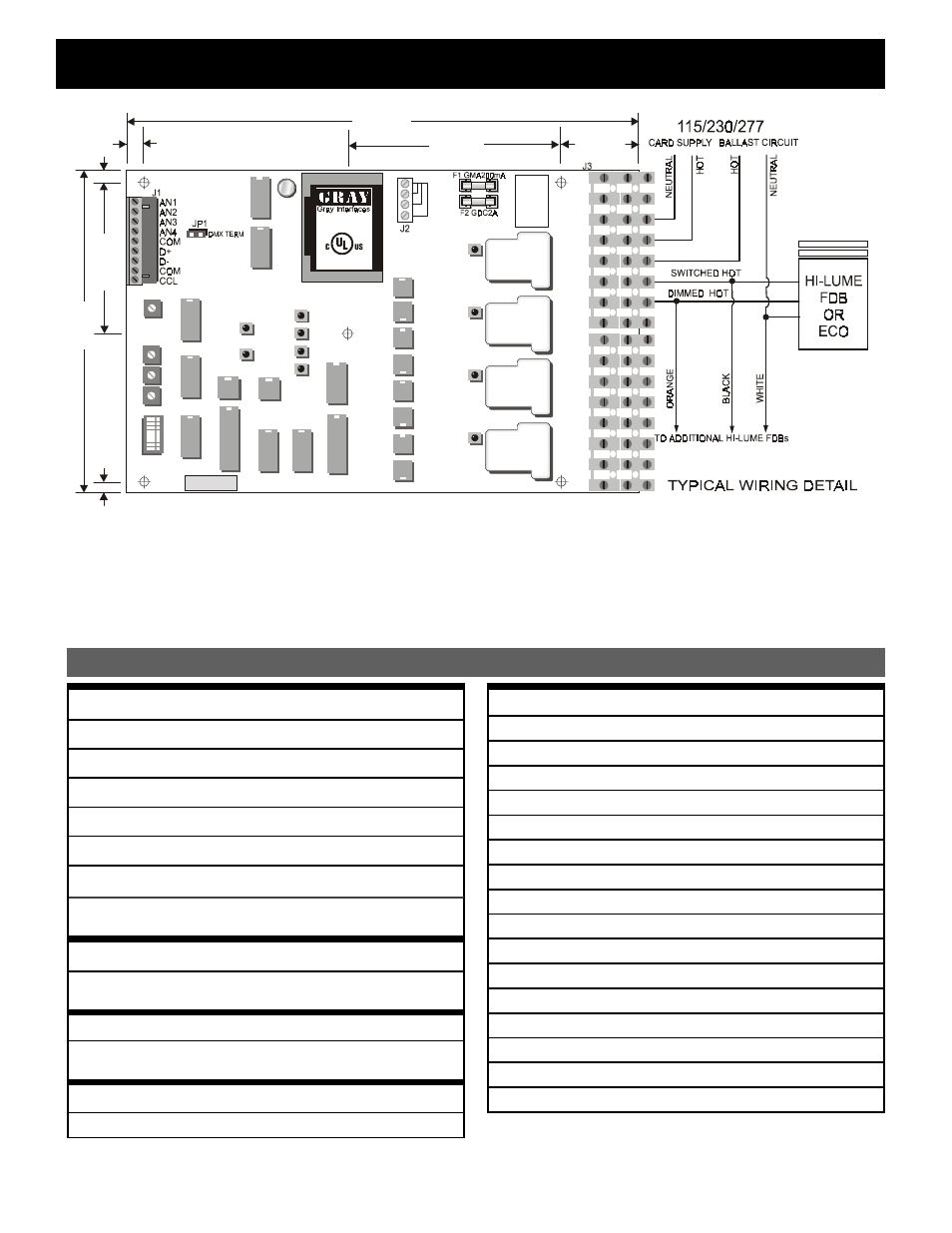
EFBC-4L FLUORESCENT DIMMING BALLAST CONTROLLER Configuration
3?>>53D?B<575>4
CONNECTOR J1
AN1-4
0-10VDC analog inputs
COM
Analog input common
D+
DMX Data+ input signal
D-
DMX Data- input signal
COM
Data common
CCL
Contact closure input (switch to COM)
CONNECTOR J2
JUMPER TO SELECT CORRECT CARD POWER
SUPPLY VOLTAGE
JP1
DMX Termination (shorted = terminated)
JP2
FACTORY USE ONLY
Use Class 2 or Limited Voltage/Limited Current
Source only
CAUTION:
1) Before applying power, ensure that J2 is set for the correct supply voltage or damage will result
2) Use Stranded Conductors only, Rated Min 75° C / 167° F
WARNING:
1) Use only with Lutron Hi-Lume
®
FDB or ECO 10™ Electronic Ballasts
GND
AC Ground
GND
AC Ground
NEUT
Card power supply NEUTRAL input
LINE
Card power supply LINE input
SH1A
Circuit 1 AC hot circuit
SH1B
Circuit 1 switched hot
DH1
Circuit 1 dimmed hot
SH2A
Circuit 2 AC hot circuit
SH2B
Circuit 2 switched hot
DH2
Circuit 2 dimmed hot
SH3A
Circuit 3 AC hot circuit
SH3B
Circuit 3 dimmed hot
DH3
Circuit 3 dimmed hot
SH4A
Circuit 4 AC hot circuit
SH4B
Circuit 4 switched hot
CONNECTOR J3
DH4
Circuit 4 dimmed hot
Hi-Lume
®
and Eco-10™ are registered trademarks of Lutron Electric Company Inc.
O P 4
R EV.6 9824
O P 3
O P 2
O P 1
LIN E
12 0V
24 0V
27 7V
G N D
G N D
N E U T
LIN E
S H 1 A
S H 1 B
D H 1
S H 2 A
S H 2 B
D H 2
S H 3 A
S H 3 B
D H 3
S H 4 A
S H 4 B
D H 4
[
5(
/$
<
/(
9(
/
6:
6:
6:
6:
6:
0
2
'(
6(
/(
&7
[
[
R UN
F L1
F L2
F L3
F L4
R xD
µ
F
or
c
o
nt
in
ued
pr
ot
ec
tion
agai
ns
t r
is
k of
fi
re
,
repl
ac
e onl
y
w
ith
s
a
me
ty
p
e
&
r
a
tin
g
s o
f fu
se
.
F
1:
250 V
/
2
0
0 mA
F
2:
250 V
/
2
A
S N S e ria l #
M O D E L #:
E F B C 4 L
L is te d Ind u s tr ia l
C on tro l E q u ip m e nt
4 0 LJ