Low voltage, Power up and test, Document wiring – Pathway DMX Relay Cabinets User Manual
Page 3: 3figure 1 – typical wiring — low-voltage switches, Push-on terminals and wire ties
3
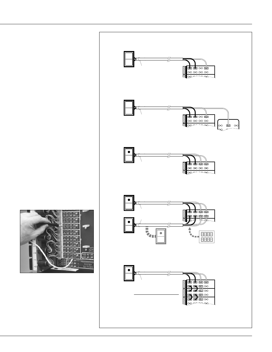
Figure 1 – Typical Wiring — Low-Voltage Switches
24V
24V RECT
WHITE
ACCESSORY
POWER SUPPLY
RED
BLACK YELLOW WHITE
2
RED
BLACK
YELLOW
WHITE
1
#20/3 AWG
1600 FEET MAXIMUM DISTANCE
HSSW3 (standard class)
HSSW3P (plenum applications)
RED
BLACK YELLOW WHITE
2
RED
BLACK
YELLOW
WHITE
1
#20/4 AWG
1600 FEET MAXIMUM DISTANCE
HPSW4 (standard class)
HPSW4P (plenum applications)
RED
BLACK YELLOW WHITE
2
RED
BLACK
YELLOW
WHITE
1
#20/4 AWG
1600 FEET MAXIMUM DISTANCE
HPSW4 (standard class)
HPSW4P (plenum applications)
RED
BLACK
YELLOW
WHITE
2
RED
BLACK
YELLOW
WHITE
1
#20/4 AWG
MAXIMUM DISTANCE (See below)
RED
BLACK
YELLOW
WHITE
3
RED
BLACK YELLOW WHITE
2
RED
BLACK
YELLOW
WHITE
1
#20/4 AWG
1600 FEET MAXIMUM DISTANCE
HOSW4 (standard class)
HOSW4P (plenum applications)
STANDARD SWITCH
LOCATION SWITCH
SINGLE SWITCH WITH
PILOT INDICATION
MULTIPLE SWITCHES
CONTROLLING
SINGLE RELAY
SINGLE (OR MULTIPLE)
SWITCH CONTROL
OF A GROUP
(BLUE)
FOR MORE THAN
TWO SWITCHES,
SPLICE CONTROL
LEADS
FOR MASTER PLATE,
USE HMSW25(P)
NUMBER
RELAYS
PARALLEL
2
4
6
8
10
MAXIMUM
DISTANCE
WITH #20/4
750 FEET
325 FEET
180 FEET
110 FEET
65 FEET
MAXIMUM
DISTANCE
WITH #16/4
1900 FEET
825 FEET
450 FEET
275 FEET
160 FEET
Note: Relays 1, 2 and 3
are now permanently
wired as a group.
You can’t control them
individually.
If the pilot contacts are
wired in parallel as above,
turning ON any relay in
the group will cause the
pilot to light.
Test relays by touching each red and black switch
input terminal with a jumper connected to any white
terminal in the panel.
HINxxy12BC/24BC/48BC
Lighting Control Panel Interior — Installation and Setup
Wiring
Line voltage
Before making connections to the
relays make sure that none of the
load circuits are shorted or miswired.
Connect the lighting circuits to the relay
SPST output terminals. Wire the power
supply, following the instructions which
accompany the unit. Connect the ground
wire to the stud provided in the tub.
Low voltage
Wire switches as shown in Figure 1. Wire
sensors and other low-voltage control
devices as shown in the installation
instructions accompanying the devices.
Use
3
⁄
16
" push-on terminals and wire ties.
Power Up and Test
Apply power to the power supply only
Using a low-voltage jumper attached to
any WHITE terminal, touch all of the
switch input RED terminals, and then
repeat for the BLACK terminals. The
relays should click on, then off. Confirm
by measuring the line-voltage termina-
tions of the relay. Test the operation of
each low-voltage switch, sensor and
other control device according to the
individual installation instructions.
Document Wiring
Record the circuits controlled by each
relay on the Relay Schedule card
provided with these instructions and then
place it in the plastic sleeve attached to
the inside of the panel cover.