Environment, Relays, Power supply – Pathway DMX Relay Cabinets User Manual
Page 2: Mounting
2
HINxxy12BC/24BC/48BC
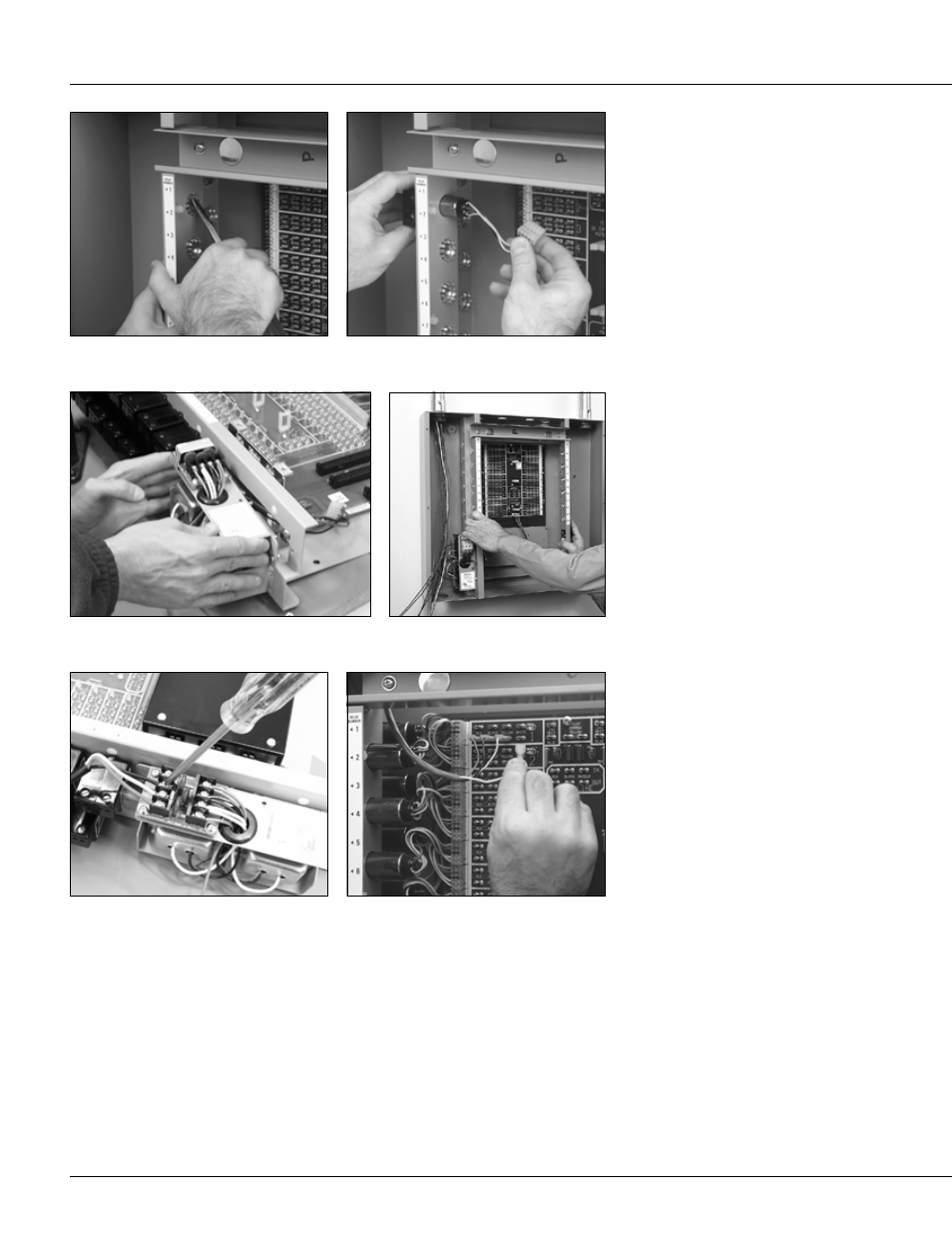
Lighting Control Panel Interior — Installation and Setup
Remove knockouts as required.
Install relays in the frame if necessary.
Install the power supply.
Mount the interior to the studs in the tub
with the hardware supplied.
Making sure all power is off, connect lighting circuit
wiring to the relays and line-voltage wiring to the
power supply.
Connect low-voltage wiring from switches, sensors
and other input devices to the terminals on the
motherboard.
This interior is intended for field
installation within the enclosure of
another product.
Refer to installation instructions
INHTUB and INHCVR for installation
of the Watt Stopper Tubs and Covers.
The following instructions assume
that a UL listed enclosure has been
properly installed.
CAUTION: Make sure all power is off
before wiring. Do not energize wiring
until the unit is fully assembled.
Conform to all applicable codes.
Environment
• 32
°
to 131
°
F (0
°
to 50
°
C)
• 95% relative humidity
• 15 volts/meter, 10 KHz maximum RFI
Relays
Use only Reliant Relay H2R7P/H2R9P
or GE RR7P/RR9P relays. Remove only
as many knockouts as required. From
the line-voltage side, feed the low-
voltage relay connector and leads
through the hole and plug the connector
to the appropriate relay termination on
the motherboard. Push the relay into the
hole so the retainers hold it in position.
Power Supply
Attach the HPSM115/277 power supply
to the bottom of the frame on a 12-relay
interior, or to the left side of the frame on
a 24- or 48-relay interior, and plug the
low-voltage connector to the termination
marked J1 on lower center of the
motherboard.
Mounting
Mount the interior in the tub and secure
it to the studs with the hardware supplied.
Make sure that all line- and low-voltage
wiring is confined to the appropriate areas.