Applying power, 1 connecting to earth ground, Hapter – Beijer Electronics QTERM®-A12 User Manual
Page 11: Pplying, Ower
QTERM-A12 Terminal
5
C
HAPTER
3
A
PPLYING
P
OWER
Power is supplied to the QTERM-A12 terminal via the COM1 serial port connector or the
3-pin power terminal strip for input power, return and chassis ground. The QTERM-A12 may
also be equipped with an optional Power-over-Ethernet (PoE) interface. When powered by the
3-pin power terminal strip or the COM1 serial port, the QTERM-A12 has a 10- to 32-volt DC
input range and can be powered directly from a 12- or 24-volt DC power supply (the current
will vary depending on the input voltage; see table below).
3.1 Connecting to Earth Ground
N
OTE
☞
The chassis ground connection of the QTERM-A12 is electrically connected to the exposed
conductive parts of the QTERM-A12 for safety purposes. The chassis ground connection
MUST be connected to an external protective earthing system.
The QTERM-A12 has a chassis ground terminal and a chassis ground connection on the 3-pin
power terminal strip on the back of the terminal. (See
and
for the location of the chassis ground terminal and the 3-pin power terminal strip.) The
terminal should be connected to earth ground (protective earth). The chassis ground is not con-
nected to signal common of the terminal. Maintaining isolation between earth ground and
signal common is not required to operate the terminal; however, other equipment connected to
the terminal may require isolation between signal common and earth ground. To maintain iso-
C
AUTION
For Class I, Division 2 installations:
Do not connect or disconnect cables while power is applied unless the area is known to be
non-hazardous.
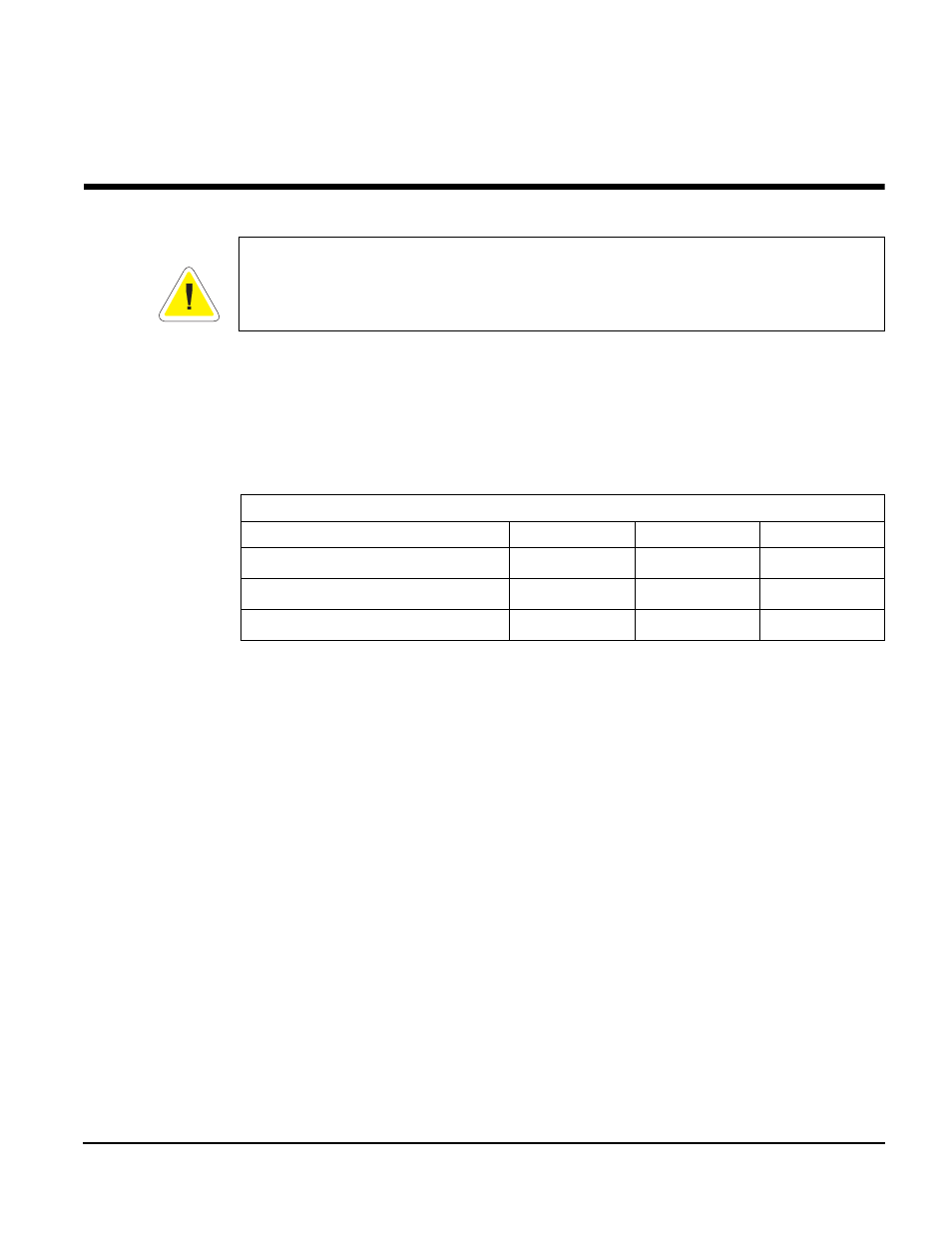
Power Consumption
Terminal
12 VDC
24 VDC
PoE (48 VDC)
Standby
1
1. Standby power consumption is measured when the display has been powered down and the
operating system has entered system idle mode.
1.3 W
1.6 W
3.0 W
Typical
2
2. Typical power consumption is measured when the display is at full brightness and a polygon
drawing application is running.
8.5 W
9.1 W
10.5 W
Estimated Maximum
3
3. Estimated maximum power consumption is measured with serial, USB and Ethernet commu-
nications active. In addition, several applications are running including video with full volume
and two USB mass storage loads are being powered.
12.1 W
13.1 W
14.2 W