Bike haven, American bicycle security company – American Bicycle Security Company Bike Haven User Manual
Page 4
American Bicycle Security Company
P.O. Box 7359
Ventura, CA 93006
Ph: (800) 245-3723 or (805) 933-3688
Fax: (805) 933-1865
Bike Haven
Installation Instructions –
Starter Section
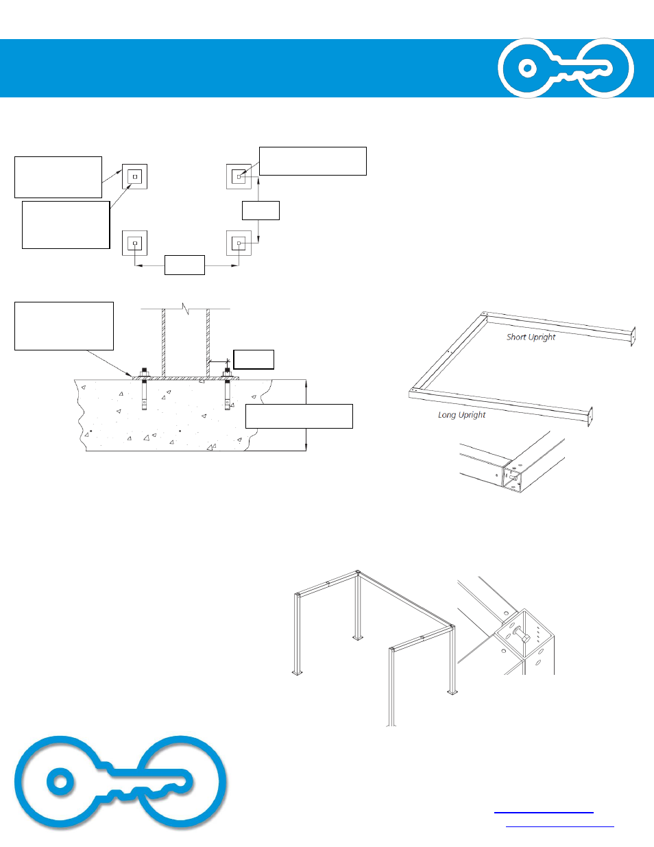
1. Customer is responsible for preparing the slab with minimum
strength of 2500psi as shown
HSS 4” X 4” X 3/16” Typical
Column in Weldment
90.00
140.00
Sidewalk Footing =
Minimum 5’ X 5’ X 5”
concrete surround at
base connection
Field Footing =
Minimum
42” X 42” X 12”
concrete surround at
base connection
10” X 10” X 3/8” Base
Plate with (4) 1/2” Dia.
Simpson Strong Bolt 2
Wedge Anchors (3 Min.
Embed) at each column
2” TYP
Sidewalk Footing = 5” Min.
Field Footing = 12” Min.
2. Lay an UPRIGHT SHORT and UPRIGHT TALL on
the ground parallel to each other and about 86”
apart. Lay a ROOF MEMBER between the two
uprights and attach with four ½” bolts (finger
tight). Note that the open square in the middle
of the ROOF MEMBER should be facing the top of
the assembly. Repeat this step for the other
UPRIGHTS and ROOF MEMBER.
3. With the help of 2 assistants, stand both
UPRIGHT ASSEMBLIES up, about 136” apart. Lift
a ROOF MEMBER LONG into place and attach it
with four ½” bolts (finger tight). Lift the
remaining ROOF MEMBER LONG pieces into place
and attach them with four ½” bolts each. If
installing additional units, repeat step 3 until all
framework is assembled.Tighten all ½” bolts.