Optional i-beam mount assembly instructions, Secondary support cable – COOK CAC User Manual
Page 4
4
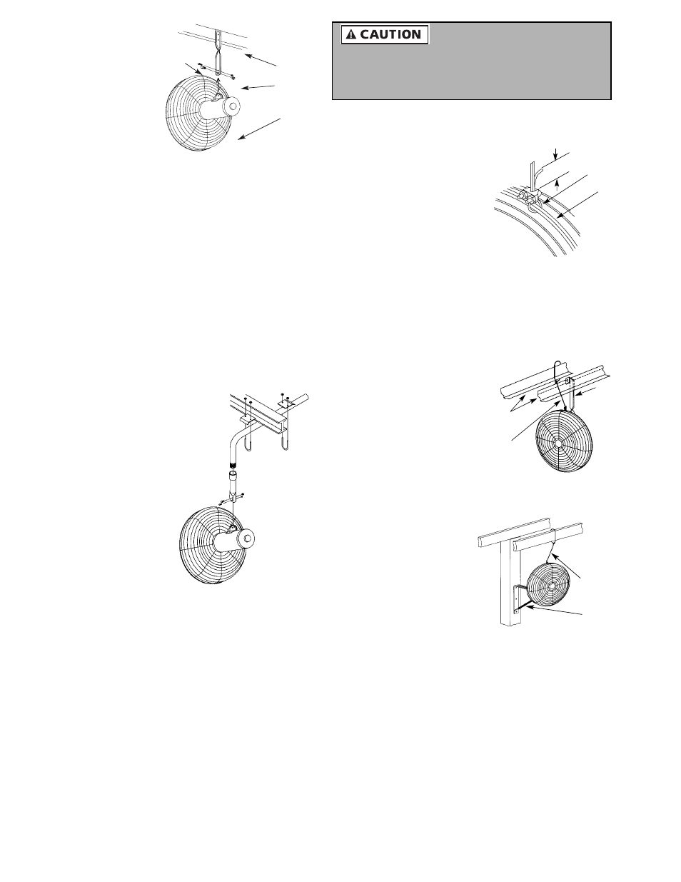
Figures 2 and 3 show typical installations using
suspension and wall/ceiling type brackets.
1. Loop one end of the cable
around the large diameter
wires of both the front and
rear guard.
(Refer to Figure 5).
2. Attach a cable clamp with
the “U” on the tail side of
the loop leaving a tail of
approximately 1 to 2”.
Tighten clamp nuts to 32
in. pounds and torque
forming a tight loop. Make sure no part of the cable
interferes with the propeller.
3. Attach a second clamp (not shown) 1 to 2” from the first
and tighten to 32 in. pounds torque. A tail of 1 to 2”
must extend past the second clamp.
4. Wrap the other end of
the cable around a
secure building joist,
beam, truss, or other
support near the fan
(Refer to Figures 6 and
7). Take up all excess
slack in the cable. If
the fan is an oscillating
model, leave enough
slack to allow free
movement through range of motion.
5. Attach the two (2)
remaining cable
clamps as indicated in
step 2. The excess tail
should be trimmed to
extend 1 to 2” past the
second clamp.
6. Check the assembly to
assure the propeller is
free of all obstructions.
NOTE: No replacement
parts available.
Use of this product does not guarantee protection
against injury of persons. Mounting of both the circula-
tor and cable could fall if subject to abuse or neglect or if
improperly installed.
1 - 2" Tail
Tight Loop
in Cable
Large
Guard
Wires
Figure 5 - Cable Clamping
Ceiling
Joists
Support
Bracket
Secondary
Support
Cable
Figure 6 - Suspension Bracket
Secondary
Support
Cable
Wall/Ceiling
Bracket
Figure 7 - Wall/Ceiling Bracket
2. Install a lag screw
through the
mounting hole to
hold the bracket
securely to the
wooden member.
3. Position
suspension
bracket in the
motor yoke and
align bolt holes.
4. Insert the larger
dia. bolt in the pivot
hole and install the lock nut finger tight.
5. Insert the smaller dia. bolt in the slot in the motor yoke
(or support bracket) and smaller hole in the pivot
bracket and install lock nut finger tight.
6. While holding the circulator at the desired angle, tighten
the smaller dia. bolt.
7. Tighten larger bolt to 200-230 in. lbs. and smaller bolt to
150-160 in. lbs., being careful to maintain desired
position.
8. Plug the power cord into a properly grounded three-
prong receptacle.
NOTE: No replacement parts available.
Optional I-Beam Mount Assembly Instructions
(Refer to Figure 4)
1. (Locate the L-shaped
pipe to the desired
location on the I-beam
flange). Install the 5/16 x
2” U-bolts over the pipe
and through the
clamping plate holes.
The flat part of the
clamping plate fits on the
I-beam flange and the
end with the slight bend
goes against the pipe.
Finger tighten the nuts
on the U-bolt.
2. Slide the clamping plate
onto I-beam flange until
U-bolts contact flange.
3. Tighten nuts on U-bolt so pipe does not move.
4. Screw on the adapter mount as far as it will go to the L-
shaped pipe. Rotate adapter mount back to desired
location and tighten set screw in pipe coupling.
5. Install circulator to adapter mount using hardware
provided. Tilt fan to desired angle and tighten larger bolt
to 200-230 in. lbs. and smaller bolt to150-160 in. lbs.
6. Install secondary support cable according to
instructions.
7. Move fan control rocker switch to OFF position and plug
power cord into a properly grounded three-prong
receptacle.
Secondary Support Cable
(For use with CAC-W, CAC-WW and CAC-WX)
To insure proper installation, carefully read and follow
steps 1 thru 6 listed.
Circulator
Mounting
Nuts
Mounting
Bolts
Beam
Figure 3 - Suspension Bracket
Installation
Figure 4 - I-Beam Installation