AltiGen comm IP 710 User Manual
Page 14
6 IP 710 Manual
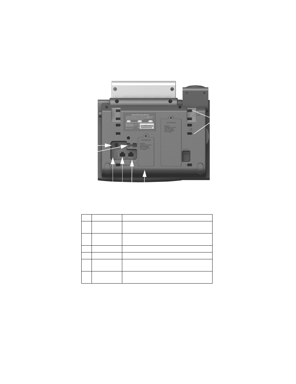
Figure 2.
IP 710 Phone, Bottom View
1
DC Port
Connects to power outlet
2
Power Cable
Restraint
Secures the power cable, preventing it from
accidentally being pulled out
3
DC/PoE Switch Switches between DC power and Power over
Ethernet
4
PC Access Port Connects to PC (10/100 Base T)
5
LAN Port
Connects to network (10/100 Base T)
6
PoE Module
Cover
Covers the optional Power over Ethernet Module
7
Slots for the
Phone Stand
Four slots on each side for inserting the phone
stand to set the phone at the desired angle
5
4
3
1
7
2
6