2 lin master selection, 3 can, 4 led – Atmel ATAVRAUTO100 User Manual
Page 8
Using the ATAVRAUTO100
2-9
ATAVRAUTO100 User Guide
7697B–AUTO–09/07
2.4.2
LIN MASTER
selection
To operate the LIN in Master mode, one 1kΩ resistor must be placed at the Master con-
nection. To do so, the MSTR jumper must be positionned as indicated in Figure 2-4.
2.4.3
CAN
Connection to the CAN network is made via the CAN connector JP2. Only the CAN- and
CAN+ are connected. The signals are routed to ATA6660 CAN high speed transceiver.
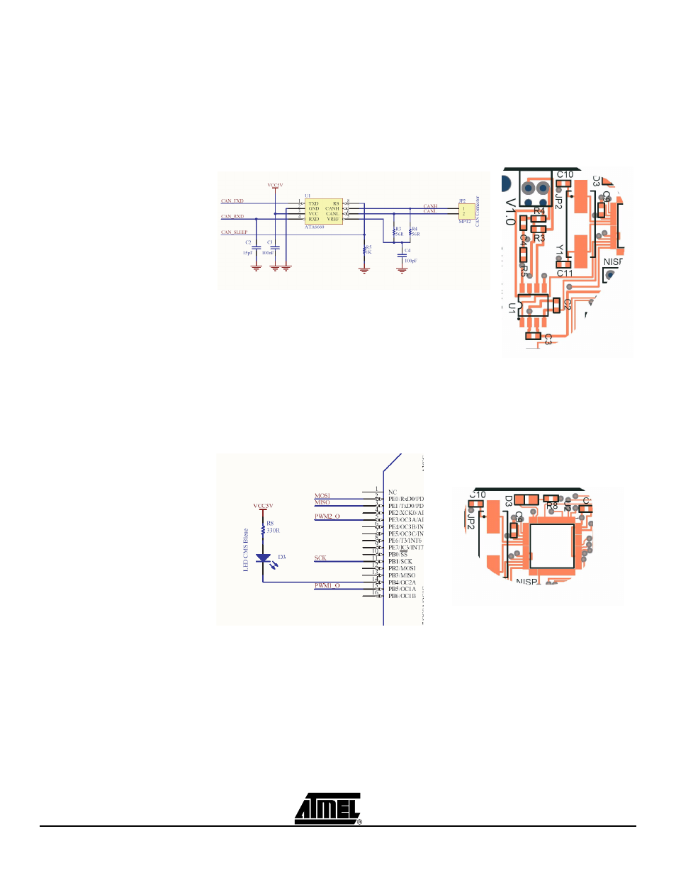
Figure 2-5. CAN High Speed connections
2.4.4
LED
The blue LED is illuminated when the ATAVRAUTO100 is correctly powered, i.e. volt-
age higher than +5V is present on the LIN connector.
Figure 2-6. VDD presence is indicated via the blue LED illumination.