Alcatel-Lucent 1850 TSS-3 User Manual
Page 5
Alcatel-Lucent 1850 TSS-3 Transport Service Switch 5
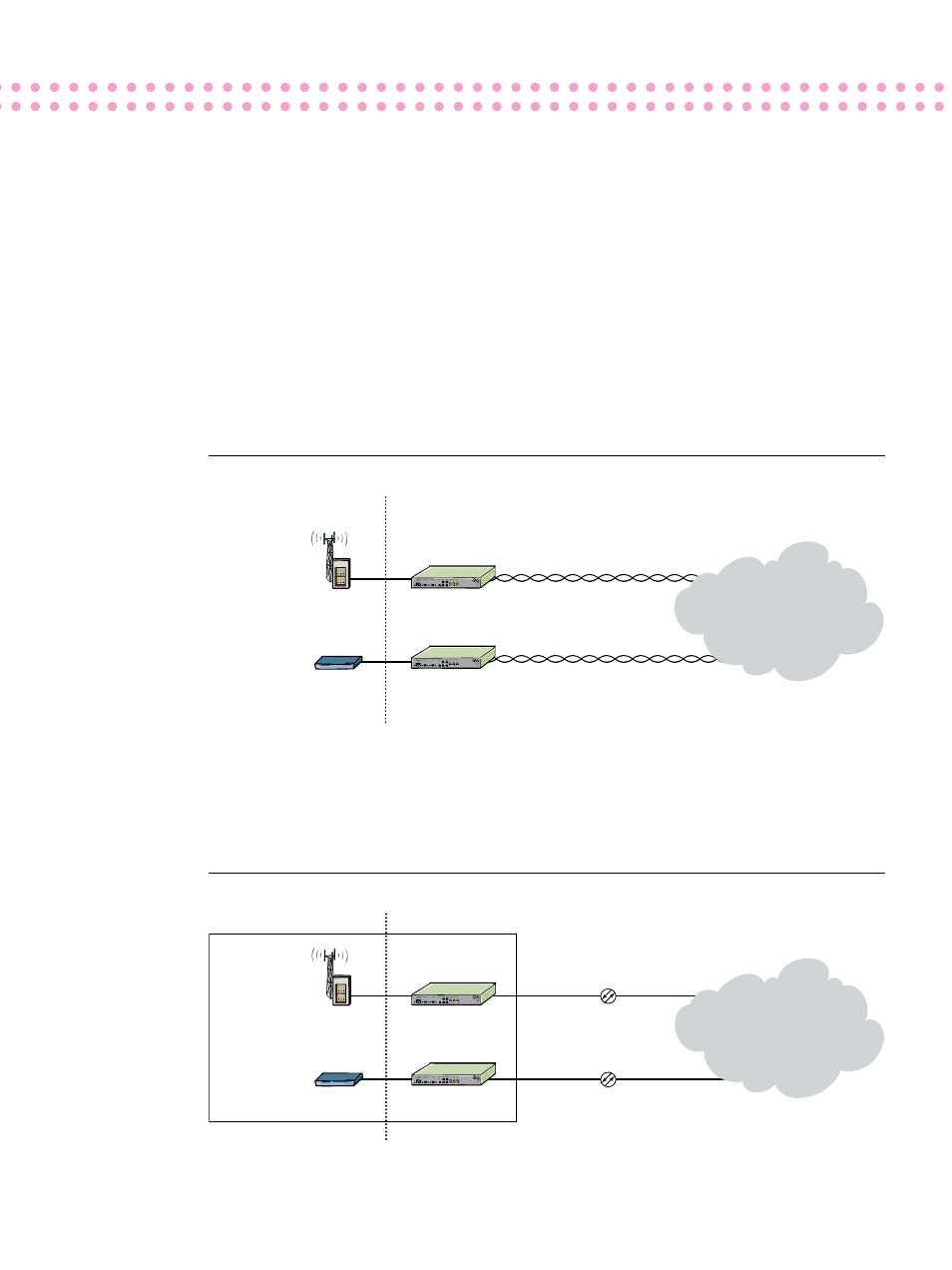
Figure 3 shows the 1850 TSS-3 in an EoPDH
configuration, installed with CPE in a standard
building or at a cellular tower. In each case, there
is a pre-existing copper connection capable of
carrying an E1/DS1 channel or an E3/DS3 chan-
nel connected to a legacy synchronous optical
network (SONET)/SDH network.
By inserting the 1850 TSS-3 into the copper
connection, EoPDH is established. Ethernet
packets are mapped to the PDH lines using a
standards-compliant mapping mechanism, VCAT/
GFP, with redundancy provided by PDH 1+1
protection. If several E1/DS1 or E3/DS3 lines are
available, they can be bonded together to create
a higher-bandwidth uplink.
Figure 3. Ethernet over PDH
In Figure 4, the 1850 TSS-3 is in the Ethernet extension configuration. In this configuration, electrically-
based FE or GigE is converted to optical Ethernet for transmission over longer distances than are
possible with copper lines. Transmission complies with the Ethernet in the first mile (EFM) standard,
bringing the service provider’s Ethernet domain right up to the customer’s building or cell site.
Figure 4. Ethernet extension
1850 TSS-3
Ethernet/
FE/GigE
Service Provider
Equipment
Ethernet over E3/DS3
Demarcation
Wireless Access
Equipment
Customer
Equipment
1850 TSS-3
Ethernet/
FE/GigE
Ethernet over E31/DS1
Legacy PDH/SDH
Network
1850 TSS-3
Ethernet/FE
Service Provider
Equipment
GigE/FE with EFM OAM
Demarcation
Wireless Access
Equipment
Customer
Equipment
1850 TSS-3
Ethernet/FE
GigE with EFM OAM
Metro Ethernet
Network
(Ethernet or MSPP
or CWDM-based)