Ariens 926502 - PB936 User Manual
Page 9
GB - 9
Remote Differential
Squeeze and hold the remote differential lever to lock
differential so both wheels drive and provide better
traction. Release the remote differential lever to allow
easier steering.
Heated Handles
Turn the heated handles
switch to the
ON (1) position to activate. Turn the
switch to the OFF (2) position to
deactivate.
IMPORTANT: Do not activate heated
handles when using brush in warm weather.
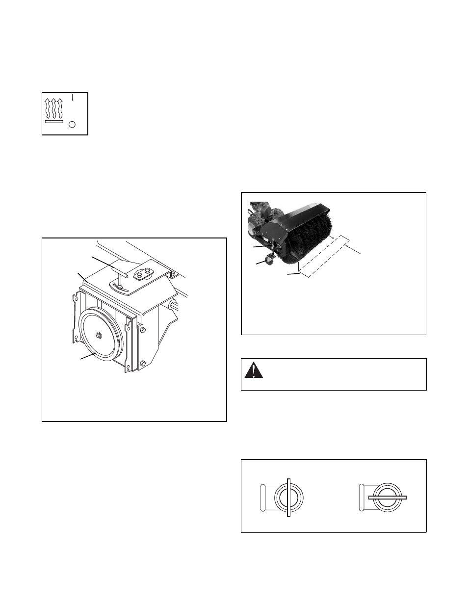
BRUSH ANGLE ADJUSTMENT
To change the angle of the brush:
1. Release the attachment clutch and then the
traction clutch.
2. Loosen the T-nut on top of the adapter frame and
turn the brush as needed. See Figure 5.
3. Retighten the T-nut.
BRUSH HEIGHT ADJUSTMENT
IMPORTANT: If brush height is set too low, brush can
drive machine rearward when attachment clutch is
engaged. Engage brush slowly with brush set at proper
height.
Adjust caster wheels to the hole nearest 1/8-1/4 inch
(3-6 mm) above surface. For hard surfaces, adjust the
caster wheels so that brush just touches surface. The
brush works best with the brush properly leveled. To
adjust the brush height:
1. Move the brush to a dusty, flat surface. Leave the
engine running.
2. Start the brush at a slow speed. Run the brush in
a stationary position for 30 seconds.
3. Lift the brush head assembly off the ground and
reverse the unit to move it away from the swept
area.
4. Stop engine and allow all moving parts to stop.
5. Check the width of the swept area. The brush
pattern should be 2-3 inches (5.08-7.6 cm) wide,
running the length of the brush. (See Figure 6).
6. To adjust, remove the caster wheel support pins
(one each side). Slide caster wheel supports up
or down as required. Align the holes in the outer
sleeve with the holes in the wheel supports.
7. Reinstall the adjustment pins at the new position.
8. Repeat steps 1- 7 until proper adjustment is
attained.
FUEL SHUT-OFF VALVE
IMPORTANT: The fuel shut-off valve MUST be in the
closed position prior to transporting the unit.
The fuel shut-off valve has two positions:
•
Closed Position: Use this position to service,
transport, or store the unit.
•
Open Position: Use this position to run the unit.
OS1950
1
2
Figure 5
1. T-Nut
2. Brush Adapter Housing
3. Attachment Drive Pulley
1
2
3
OSs0083
WARNING: AVOID INJURY. Read and
understand the entire Safety section before
proceeding.
Figure 6
1. Swept Area
2. Caster Wheel
3. Height
Adjusting Pin
1
2
3
2-3 in
(5.08-7.6 cm)
OS0061
Figure 7
OPEN
CLOSED