Maintenance, Maintenance schedule, Service position – Ariens 926502 - PB936 User Manual
Page 12
GB - 12
Ariens Dealers will provide any service or adjustments
which may be required to keep your unit operating at
peak efficiency. Should engine service be required,
contact an Ariens dealer or an authorized engine
manufacturer's service center.
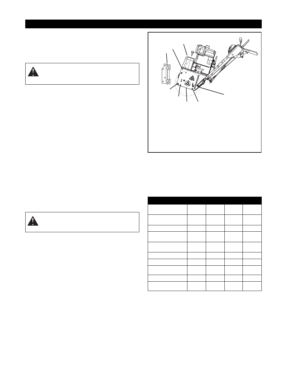
SERVICE POSITION
IMPORTANT: DO NOT tip unit up onto brush. Remove
the brush if maintenance requires tipping the unit
forward. Ensure unit is secure and will not tip over.
Strap or clamp unit onto bench if required.
To access components in the unit frame:
1. Shut off engine and allow unit to cool completely.
Place unit on a flat level surface.
2. Remove belt cover (Figure 8).
3. Remove the rear cap screws from the bottom
cover. Loosen the side cap screws and remove
the bottom cover before separating unit.
4. Loosen cap screws and carefully rotate belt
fingers away from belt and sheave (Figure 8).
IMPORTANT: Use care when rotating the belt fingers.
DO NOT bend belt fingers out of shape.
5. Remove attachment drive belt from engine
sheave (it may be necessary to turn engine
sheave using recoil starter handle).
6. Support unit frame and brush attachment.
7. Remove cap screws securing attachment to unit
frame (one on each side). Tip attachment and
frame apart on pivot rod.
8. Remove attachment belt from attachment pulley.
9. Separate frame from brush.
MAINTENANCE SCHEDULE
The chart below shows the recommended
maintenance schedule that should be performed on a
regular basis. More frequent service may be required
due to working conditions (heavy loads, high ambient
temperatures, dusty conditions, or airborne debris).
*
After first five hours of operation.
**
After first two hours of operation.
*** Grease universal joint after first 16 hours of
operation and every 8 hours thereafter.
MAINTENANCE
WARNING: AVOID INJURY. Read and
understand the entire Safety section
before proceeding.
CAUTION: Always support unit frame and
brush attachment when loosening the cap
screws holding them together.
MAINTENANCE SCHEDULE
Service Performed
Each Use
Every 5
hrs.
Every 25
hrs.
Yearly
Check Dual Handle
Interlock
•
Check Fasteners
•
Check Clutch
Operation
•
Check Clutch Spring
Adjustments
*
•
Clean Engine
•
Check Engine Oil
•
Change Engine Oil
**
•
Check Tire Pressure
•
General Lubrication
***
•
•
Figure 8
1. Belt Cover
2. Rear Cap Screws
3. Bottom Cover
4. Side Cap Screws
5. Pivot Rod
6. Brush Frame Adapter
7. Brush Mounting Cap
Screw
1
4
5
6
7
OSS0271
3
2
4