See attachment – Ariens 926502 - PB936 User Manual
Page 16
GB - 16
d.Finger tighten the jam nut, and then hold the
adjuster body with pliers and tighten the jam nut
with wrench.
6. Measure the extension of the traction drive clutch
spring.
7. Repeat step 5 until traction drive clutch spring
lengthens 1/2 -11/16 in.(12.7-17.5 mm) when the
traction drive clutch lever is engaged.
8. With the clutch disengaged, check that there is
more than 1/32 in. (0.8 mm) clearance between
friction disc and drive plate assembly.
IMPORTANT: If spring length cannot be adjusted
within specified range, see your Dealer for repairs.
ATTACHMENT DRIVE BELT
REPLACEMENT
Remove old attachment drive belt:
IMPORTANT: To avoid bending bottom cover when
tipping unit apart, support handlebars firmly and
remove bottom cover by removing six cap screws
before separating unit.
1. Follow the instructions for removing the brush
attachment from the unit frame under Service
Position.
2. Remove attachment drive belt from engine
sheave (it may be necessary to turn engine
sheave using recoil starter handle).
Install new attachment drive belt:
1. Place new attachment belt onto attachment
pulley.
NOTE: Holding down the attachment clutch lever will
make it easier to reconnect the housing and frame.
2. Tip attachment and frame back together and
secure with cap screws.
3. Place belt onto engine sheave.
4. Reposition and secure belt fingers.
IMPORTANT: Make sure belt fingers are 1/16 to 1/8 in
(1.6-3 mm) from belt when attachment clutch is
engaged.
5. Check clutch adjustment (see Attachment Clutch
Adjustment).
6. Replace belt cover.
TRACTION DRIVE BELT REPLACEMENT
IMPORTANT: To avoid bending bottom cover when
tipping unit apart, support handlebars firmly and
remove bottom cover by removing six cap screws
before separating unit.
1. Follow the instructions for removing the brush
attachment from the unit frame under Service
Position.
2. Remove attachment drive belt (see Attachment
Drive Belt Replacement on page 16).
3. To gain belt clearance, back out the stop bolt from
the frame until the drive plate assembly can
swing past it (Figure 16).
4. Pull idler away from traction drive belt and
remove belt from idler pulley, engine sheave and
driven pulley (it may be necessary to turn engine
pulley using recoil handle).
5. Install new traction drive belt onto attachment
pulley and engine sheaves.
6. Pull the drive plate assembly toward the friction
disc and tighten the stop bolt.
NOTE: Make sure the drive plate assembly return
spring remains connected to the frame.
7. Replace attachment drive belt (See Replace
Attachment Drive Belt).
FRICTION DISC REPLACEMENT
1. Place unit into service position.
2. Remove bottom cover by removing six hex bolts.
3. With axle locked, hold one wheel so friction disc
will not rotate and remove three cap screws
holding friction disc to carrier.
4. Remove both wheels.
5. Remove right and left bearing flanges from frame.
6. Slide hex shaft to the left enough to remove
pinion sprocket from hex shaft.
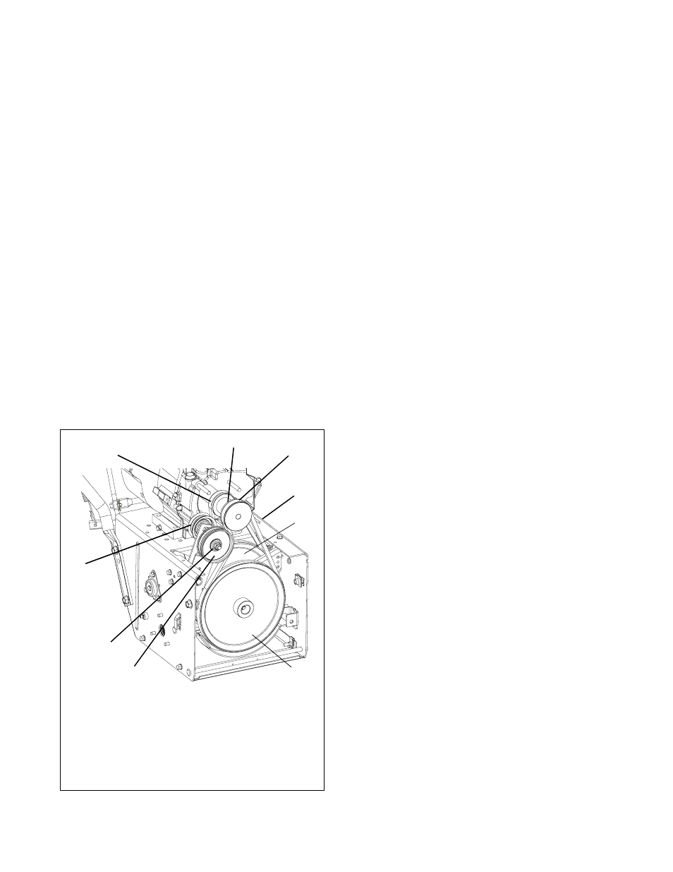
Figure 15
1. Traction Drive Belt
2. Engine Sheave
3. Attachment Drive Belt
4. Belt Finger
5. Attachment Belt Idler
6. Attachment Pulley
7. Attachment Idler
Adjustment Nut
8. Traction Belt Idler
9. Traction Drive Pulley
OS3320
1
2
3
4
5
8
9
6
7