Power control port, Computer power, Control switching – Adder Technology AdderView CATx EPS-S8 User Manual
Page 16
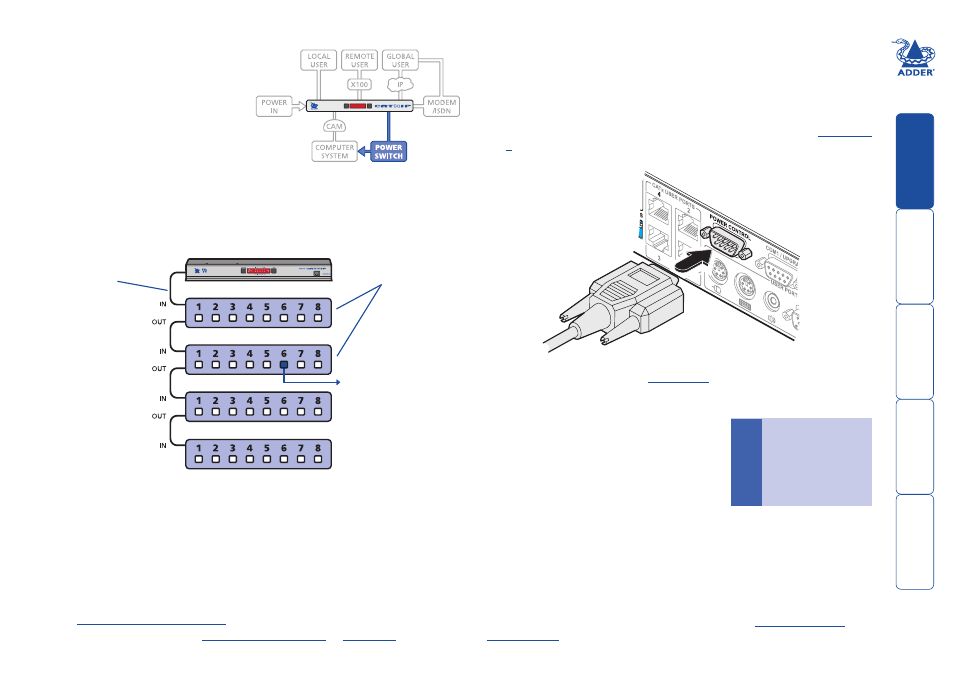
Power control port
The.AdderView.CATx.IP.models.provide.
a.serial.port.for.connection.to.one.or.
more.optional.power.control.units..
This.allows.you.to.control.the.mains.
power.being.supplied.to.the.connected.
computer(s).so.that.an.authorised.user.
can,.if.necessary,.perform.a.complete.
remote.cold.reboot.on.a.failed.system.
The.control.connector.of.the.first.power.switch.is.attached,.via.serial.cable,.to.
the.rear.panel.of.the.AdderView.CATx.IP..Any.additional.power.switches.are.
then.attached.via.a.‘daisy-chain’.arrangement.to.the.first.power.switch..Each.
power.switch.box.is.then.given.a.unique.address.and.access.to.each.power.port.
(8.ports.on.each.power.switch.box).is.gained.using.a.combination.of.the.switch.
box.address.and.the.port.number..
To connect and address the switch boxes
Note: The AdderView CATx IP unit can be powered on during this procedure,
however, the switch boxes should be switched off.
1. Mount.up.to.four.switch.boxes.in.positions.where.they.are.close.to.the.
computer.systems.that.they.will.control.and.not.too.distant.from.the.
AdderView.CATx.IP.unit.(preferably.within.2.5.metres).
2. Use.a.serial.cable.with.an.RJ9.and.a.9-pin.D-type.connector.(see.
.for.specification)..Attach.the.RJ9.plug.to.the.socket.marked.
IN
.on.the.first.
switch.box..Attach.the.other.end.to.the.socket.marked.
POWER CONTROL
.on.
the.AdderView.CATx.IP.
Power to computer
Box , port - address:
Box
Box
Box
Box
Power
switch
boxes
‘Daisy-chain’
control
connections
The.power.ports.are.connected.to.the.power.inputs.of.each.computer.system.
and.the.power.switch.box(es).are.then.connected.to.a.mains.power.supply.
IMPORTANT: Power switching devices have a maximum current rating. It is
essential to ensure that the total current drawn by the equipment connected
to the power switching device does not exceed the current rating of the power
switching device. You must also ensure that the current drawn from any mains
socket does not exceed the current rating of the mains socket.
Setting.up,.configuring.and.using.power.switching.requires.three.main.steps:
•. Connect.and.address.the.switch.boxes.
•.
•. Operate.power.switching.
.or.
3. For.each.of.the.remaining.switch.boxes.(if.used),.use.a.serial.cable.with.RJ9.
connectors.at.both.ends.(see.
.for.specification)..Attach.one.
end.to.the.socket.marked.
OUT
.of.the.previous.box.and.the.other.end.to.the.
socket.marked.
IN
.of.the.next.box..
4. Set.the.addressing.switches.on.each.switch.
box.using.the.two.micro.switches.marked.
‘Slct’.on.the.front.panel..The.box.connected.
directly.to.the.AdderView.CATx.IP.is.Box.1.
and.so.on,.down.the.daisy-chain.line.to.Box.
4.at.the.end.
5. Attach.IEC.to.IEC.power.leads.between.
each.port.and.the.power.input.socket.of.
each.computer.system.that.requires.power.
switching..Carefully.note.to.which.power.
ports,.on.which.boxes,.each.computer.system.is.connected..If.computer.
systems.have.multiple.power.inputs,.then.each.input.must.be.connected.via.
separate.ports,.which.can.be.on.the.same,.or.different.boxes.
6. Connect.each.box.to.a.suitable.mains.power.input..
Now.proceed.to.the.configuration.stage.covered.in.the.
.section.within.the.Configuration.chapter.
Box
Switch Switch .
.
1
...
Off.
Off
.
2
.
On.
Off
.
3
.
Off.
On
.
4
.
On.
On
Off = switch upwards
On = switch downwards
Switch is on the left side
AdderView CATx
rear panel
Serial cable to first
power switch box
- AdderView CATx CATX-PS2 AdderView CATxIP 1000 AdderView CATx PSU-IEC-5V6A AdderView CATx X200A/R AdderView CATx X100A/R AdderView CATx CATX-PS2A AdderView CATx CATX-USB AdderView CATx EPS-M8 AdderView CATx AVX4016 AdderView CATx CATX-USBA AdderView CATx X100R AdderView CATx CATX-SUNA AdderView CATx RS232 AdderView CATx AVX4016IP AdderView CATx X200R AdderView CATx X100AS/R AdderView CATx X200AS/R