Ariens Sno-Thro 921001 - ST824E User Manual
Page 28
GB - 28
2. Tip housing and frame back together and secure
with hex bolts.
3. Place belt onto engine sheave.
4. Reposition and secure belt fingers.
IMPORTANT: With clutch lever engaged, belt finger on
the side opposite the belt idler should be less than
1/8 in. (3 mm) from belt, but not touching the belt.
Adjust belt finger as necessary.
5. Check adjustment. See Attachment Clutch/Brake
6. Reconnect chute crank and secure with spring
clip. Reconnect chute lock cable and deflector
cable.
7. Replace belt cover.
TRACTION DRIVE BELT REPLACEMENT
NOTE: Replacement will be easier with housing and
frame tipped apart and bottom cover off.
1. Remove attachment drive belts (see Attachment
Drive Belt Replacement on page 27).
2. To gain belt clearance, remove swing gate spacer
and slide drive plate over so that finger clears
stop hole in frame and can swing past it. See
Figure 45.
3. Pull idler away from traction drive belt and
remove belt from idler pulley, engine sheave and
driven pulley (it may be necessary to turn engine
pulley using recoil handle).
4. Install new traction drive belt onto attachment
pulley and engine sheaves.
5. Swing drive plate toward friction disc until finger
lines up with stop hole in frame. Slide drive plate
over, inserting finger into stop hole. Reinstall
drive plate spacer.
NOTE: Make sure the drive plate assembly return
spring remains connected to the frame and nylon
bushing is in drive plate pivot hole.
6. Replace attachment drive belt (See Attachment
Drive Belt Replacement on page 27).
FRICTION DISC REPLACEMENT
1. Shut off engine, remove key, disconnect spark
plug wire and allow unit to cool completely.
2. Place unit into service position on a level surface.
3. Remove both wheels.
4. Remove bottom cover by removing six hex bolts.
WARNING: AUGER / IMPELLER MUST
STOP within 5 seconds when attachment
clutch lever is released or unit damage or
serious injury may result.
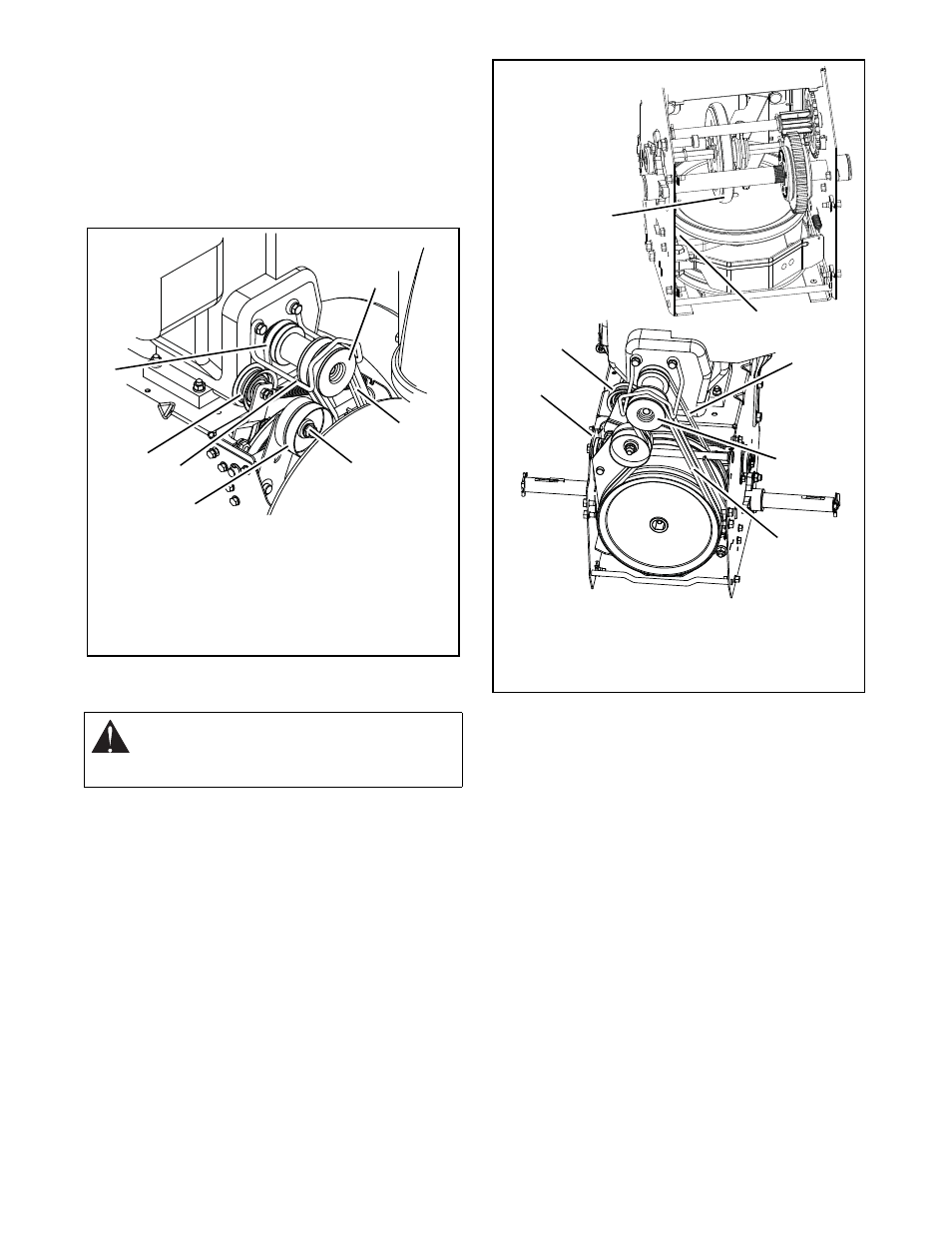
Figure 44
OS7198
1. Traction Drive Belt
2. Engine Sheave
3. Attachment Drive Belts
4. Belt Finger
5. Attachment Belt Idler
6. Attachment Idler
Adjustment Nut
7. Traction Belt Idler
2
1
3
4
5
6
7
Figure 45
OS7144
1. Spacer
2. Drive Plate Assembly
3. Traction Belt Idler
4. Attachment Drive Belts
5. Traction Drive Belt
6. Engine Sheave
7. Friction Disc
2
3
5
6
1
7
4