Video component hookups 6, Video component hookups, Getting started – Sony STR-DE435 User Manual
Page 6: Hookups, Where do i go next, Overview
6
Getting Started
Receiver
CD player
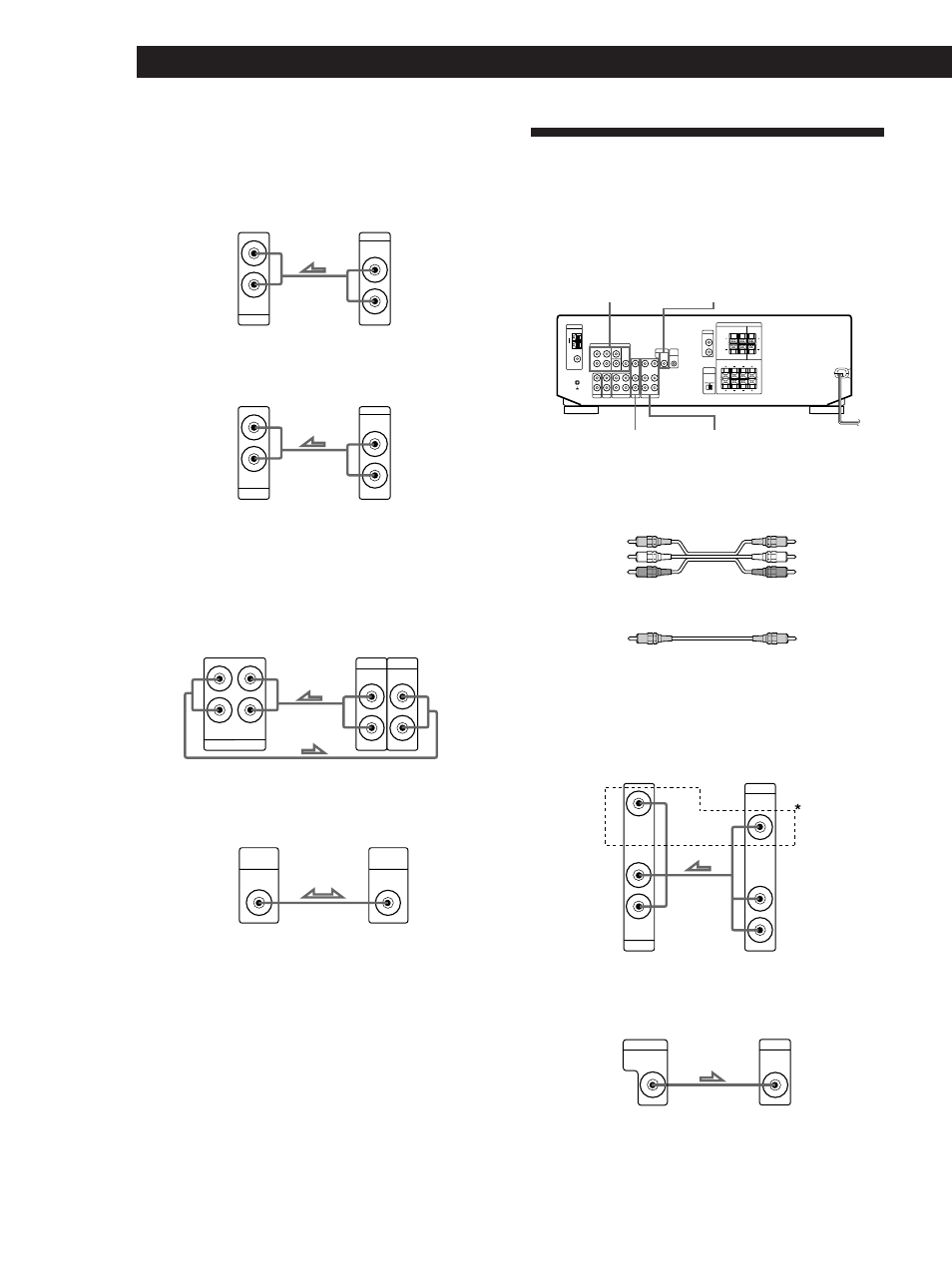
Hookups
The arrow ç indicates signal flow.
CD player
Turntable (except STR-DE435)
• If your turntable has an earth lead
To prevent hum, connect the earth lead to the
y ground
terminal on the receiver.
MD recorder or Tape deck
CONTROL A1 II (STR-DE535 only)
If you have a CONTROL A1 II-compatible Sony CD player,
MD recorder or tape deck
Use a CONTROL A1 II cord (not supplied) to connect the
CTRL A1 II jack on the CD player, MD recorder or tape deck
to the CTRL A1 II jack on the receiver. Refer to the separate
manual “CONTROL-A1 II Control System” and the
operating instructions supplied with your CD player, MD
recorder or tape deck for details.
Where do I go next?
Go on to the next section to connect video components to
enjoy surround sound when watching/listening to TV
programs or video tapes.
Receiver
Turntable
MD recorder or Tape deck
Receiver
Receiver
CD player, MD recorder
or Tape deck
Video Component Hookups
Overview
This section describes how to connect video
components to the receiver. For specific locations of the
jacks, see the illustration below.
What cables will I need?
• Audio/video cable (not supplied) (1 for each TV tuner or
Satellite receiver; 2 for the VCR)
• Video cable (not supplied) (1 for a TV monitor)
Hookups
The arrow ç indicates signal flow.
TV/SAT
* except STR-SE491
MONITOR (except STR-SE491)
MONITOR (except STR-SE491)
VIDEO
TV/SAT
5.1 CH/DVD
Yellow
Yellow
Yellow
White (L)
Red (R)
Yellow
White (L)
Red (R)
Receiver
TV tuner or Satellite
receiver
TV monitor
Receiver
CD
AUDIO IN
L
R
OUTPUT
LINE
L
R
PHONO
AUDIO IN
L
R
OUTPUT
LINE
L
R
IN
OUTPUT
LINE
INPUT
LINE
L
R
MD/TAPE
REC OUT
L
R
CTRL
A1
II
CTRL
A1
II
AUDIO IN
L
R
TV/SAT
VIDEO IN
AUDIO
OUTPUT
VIDEO
L
R
MONITOR
VIDEO
OUT
INPUT
VIDEO