ARM IM-AD1 User Manual
Page 40
Hardware Reference
3-16
Copyright © 2001-2003. All rights reserved.
ARM DUI 0163B
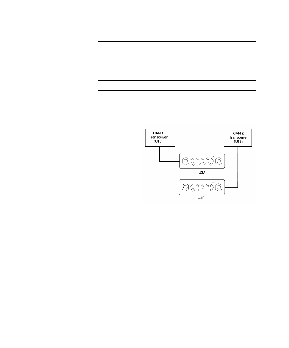
You connect the CAN interfaces through the 9-pin D-type plugs J3A (top) and J3B
(bottom), with CAN1 connecting to J3A.
Figure 3-9 shows the pin locations for this type of connector.
Figure 3-9 CAN connector pin locations
CAN2_nINT
IM_BBANK28
CAN2 interrupt
CAN1_RXD
IM_BBANK29
CAN1 receive data
CAN2_RXD
IM_BBANK30
CAN2 receive data
Table 3-8 CAN interface signal assignment (continued)
Signal
EXPIM
connector
Description