Alliance Laundry Systems UW125VV User Manual
Page 16
© Copyright, Alliance Laundry Systems LLC – DO NOT COPY or TRANSMIT
Operation
F232123
14
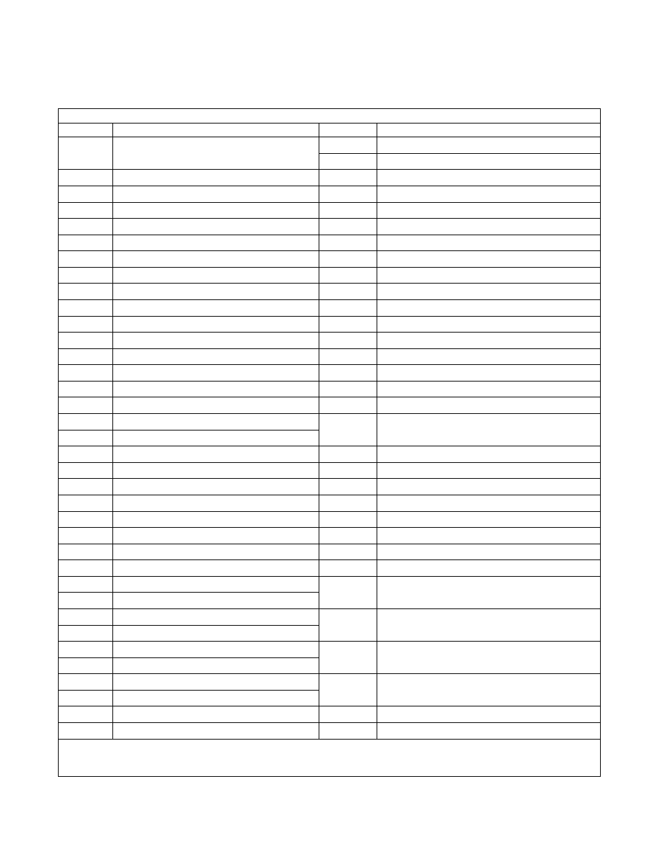
Table 2 lists the various displays and what they mean.
The operator should become familiar with these
computer displays.
Table 2
Display Indications
Display
Meaning
Display
Meaning
FPC3, bP3
Program identification code (ROM)
These are examples only.
Lo
Low water level
n
Ed
Medium water level
Hold
Wait...power has just been turned on.
HI
High water level
CY
Cycle (followed by two-digit number)
SUP1
Supply 1
tESt/CYC*
Test cycle selected.
SUP2
Supply 2
FAr
Degrees Fahrenheit
SUP3
Supply 3
CEL
Degrees Celsius
SUP4
Supply 4
HEAt
Auxiliary heat enabled.
SUP5
Supply 5 (SETUP option)
noHt
Auxiliary heat disabled.
SUP6
Supply 6 (supply 1 and 5)
tFIL
Temperature-controlled fill enabled.
SUP7
Supply 7 (supply 3 and 4)
ntFL
Temperature-controlled fill disabled.
SLo/For**
Gentle wash speed, forward direction
CooL
Automatic cool-down enabled.
SLo/rEv**
Gentle wash speed, reverse direction
noCL
Automatic cool-down disabled.
nor
n
/For
Normal wash speed, forward direction
Ag 1
Agitation 1 selected (90% agitation).
nor
n
/rEv
Normal wash speed, reverse direction
Ag 2
Agitation 2 selected (33% agitation).
drAI
Drain enabled.
Ag 3
Agitation 3 selected (10% agitation).
nodr
Drain disabled.
Ag 4
Agitation 4 selected (6.7% agitation).
dISt
Distribution (load balancing before extract)
AgSn
Agitation speed normal
SPIn/tI
n
E*
Reads “SPIn” for one second, then “tI
n
E” followed by
time for spin.
AgSL**
Agitation speed low
PU
n
P
Pump output enabled (future use only).
SPn1
Lowest of three spins
nP
n
P
Pump output disabled (future use only).
SPn2
Middle of three spins
PrE
PreWash segment (1st of 11 segments)
SPn3
Highest of three spins
UASH
Wash segment (2nd of 11 segments)
STOP
Stop routine
FIL1
First fill (3rd of 11 segments)
SdLY
Spin coast delay
FIL2
Second fill (4th of 11 segments)
donE
Cycle and stop routine have ended.
FIL3
Third fill (5th of 11 segments)
dFLt
Drive fault detected.
FIL4
Fourth fill (6th of 11 segments)
door
Door not properly closed.
FIL5
Fifth fill (7th of 11 segments)
bAL/FAIL*†
Balancing routine failed during test cycle after
7 attempts to balance load.
FIL6
Sixth fill (8th of 11 segments)
FIL7
Seventh fill (9th of 11 segments)
FILL/STOP*
Programmed water level not reached after
30 minutes.
FIL8
Eighth fill (10th of 11 segments)
FIL9
Ninth fill (11th of 11 segments)
FULL
The computer detects low water level or higher when
none should be present.
CFIL
Cold fill
bFIL
Warm fill (both hot and cold)
rotA
Computer detects possible rotation of motor when there
should be none.
HFIL
Hot fill
AFIL
Auxiliary fill (SETUP option)
tSFL
Temperature sensor failure or temperature out of range.
SPC?
Special test cycle function (if present, ignore)
bAL?
Special test cycle function (if present, ignore)
* Display indications separated by a slash represent a flashing display.
** For UW100VV and UW125VV models, the washer-extractor will operate at normal wash speed regardless of the speed settings.
† This occurs only in the TEST cycle and only if the AC inverter drive balance detection is used. If the AC inverter drive balance detection is not used, this
will NOT appear during the TEST cycle (note, there are two types of balance systems).