English – Agri-Fab 45-02114 User Manual
Page 6
6
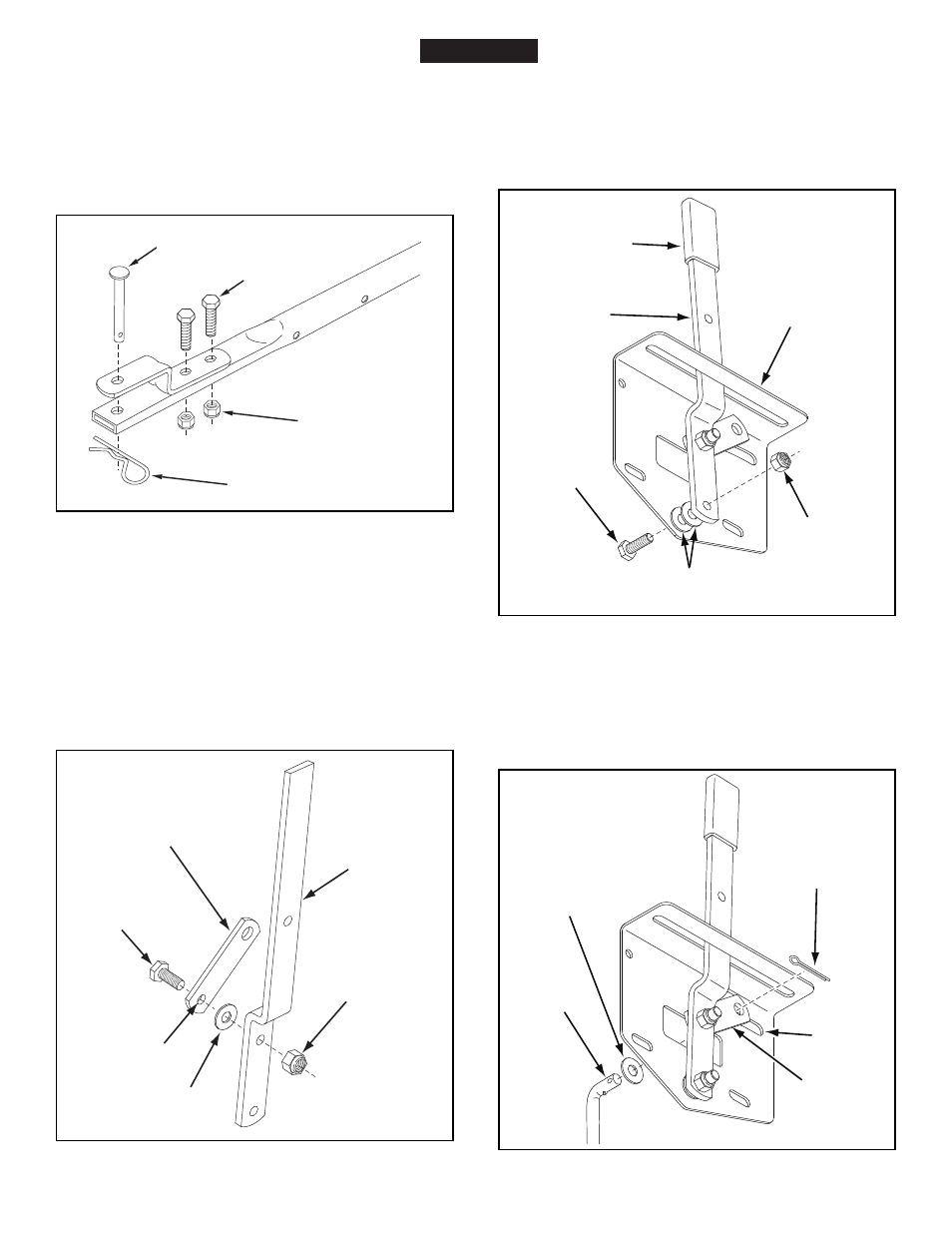
17. Place a 5/16" flat washer (F) onto the end of the flow
control rod. Insert the end of the rod through the slot in
the flow control mounting bracket and through the hole
in the flow control link (O). Secure with a 3/32" x 3/4"
cotter pin (H). See figure 8.
FIGURE 8
11. Turn the spreader upright on its wheels.
12. Assemble the hitch bracket to the top of the hitch tube
using two 1/4" x 1" hex bolts (B) and 1/4" nylock nuts
(D). See figure 5.
13. Assemble the hitch pin (K) through the hitch bracket
and the hitch tube and secure with the hair cotter pin
(J). See figure 5.
FIGURE 5
14. Assemble the flow control link (O) (end with small hole)
to the flow control arm using a 1/4" x 1" hex bolt (B),
a nylon washer (E) and a 1/4" nylock nut (D).
Tighten
carefully. The flow control link should not be loose but
should pivot with no more than slight resistance. See
figure 6.
FIGURE 6
15. Assemble the flow control arm to the flow control
mounting bracket using a 1/4" x 1" hex bolt (B), two
nylon washers (E) and a 1/4" nylock nut (D) as shown in
figure 7.
Tighten carefully. The flow control arm should
pivot with a slight resistance.
16. Assemble the vinyl grip (P). See figure 7.
FIGURE 7
(B) 1/4" x 1"
HEX BOLT
(D) 1/4"
NYLOCK NUT
FLOW CONTROL
MOUNTING
BRACKET
FLOW
CONTROL
ARM
(E) 2 NYLON
WASHERS
(P) VINYL GRIP
ENGLISH
(B) 1/4" x 1"
HEX BOLT
(D) 1/4" NYLOCK
NUT
(K) HITCH PIN
(J) HAIR COTTER PIN
(O) FLOW CONTROL
LINK
FLOW
CONTROL
ARM
(D) 1/4"
NYLOCK NUT
(B) 1/4" x 1"
HEX BOLT
SMALLEST
HOLE
(E) NYLON
WASHER
FLOW
CONTROL
ROD
(O) FLOW
CONTROL
LINK
(H) 3/32"
COTTER
PIN
(F) 5/16" FLAT
WASHER
SLOT